Option 100 Fault Location and SRL 1-15
Introduction and Measurement Theory
Cable Impedance and Structural Return Loss Measurement Theory
The default values for the connector model are 0.00 mm length, and
0.00 pF capacitance (no compensation).
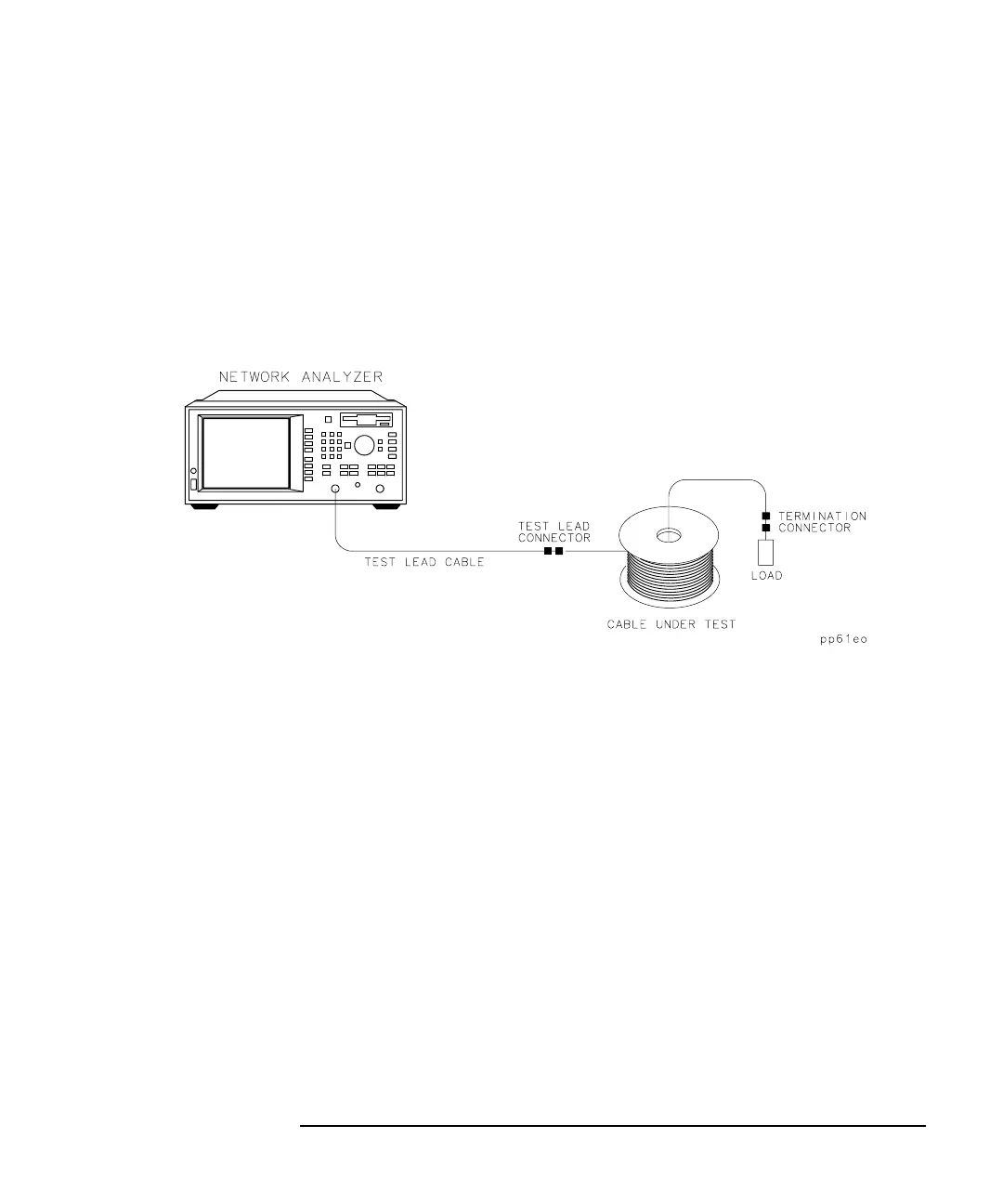
When measuring spools of cable, typically two connectors are used: the
test-lead connector and the termination connector. (See Figure 1-3.)
These connectors provide the cable interface and are measured as part of
the cable data.
Figure 1-3 Basic SRL Measurement Setup and Connections
Often, slight changes in the test-lead connector can cause significant
changes in the values of structural return loss measured at high
frequencies. This is because the reflection from a connector increases for
high frequencies. In fact, the return loss of a test-lead connector can
dominate the SRL response at frequencies above 500 MHz. This is where
training, good measurement practices, and precision cable connectors are
needed, especially for measurements up to 1 GHz. Precision connectors
are required to provide repeatability over multiple connections. Slip-on
connectors are used to provide rapid connections to the cables, but
require careful attention in obtaining good measurement data.
Repeatability of measurement data is directly affected by the connector's
ability to provide a consistently good connection. This is the major cause
of repeatability problems in SRL measurements.
Effects of the test-lead connector at the measurement interface are
observed as a slope in the noise floor at higher frequencies.
(See Figure 4-6 on page 4-11.) By observing the SRL measurement
display and slightly moving the connector, the effects of the connection
can be observed at the higher frequencies. The test-lead connector should
be positioned to obtain the lowest possible signal level and the flattest