4-10 Option 100 Fault Location and SRL
Making SRL Measurements
How to Make and Interpret SRL Measurements
Connector Fault Display
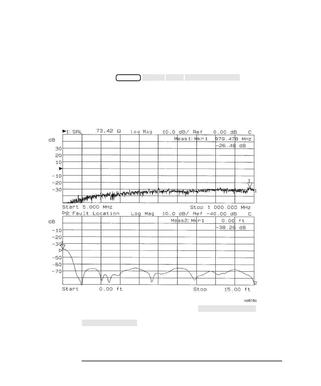
After the calibration is completed, the test lead cable (if used) has been
verified and the equipment is connected, display the connector response
by selecting . Fault location
from 0.0 to 15.0 ft. will be displayed on the second measurement channel
and a marker will be placed at 0.0 ft. The response of the connector is
equal to the return loss read by the marker at a distance of 0.0 ft. See
Figure 4-5.
Figure 4-5 Connector Fault Display
To enter the connector model menu, press . As the
following connector modeling procedures are performed, the
display will allow you to monitor the connector
response improvements.
When the optimum connector response has been obtained, refer to “SRL
Measurement Uncertainty vs Connector Fault” on page 9-8.
BEGIN
 Loading...


