Option 100 Fault Location and SRL 4-15
Making SRL Measurements
How to Make and Interpret SRL Measurements
Connector L and C Values
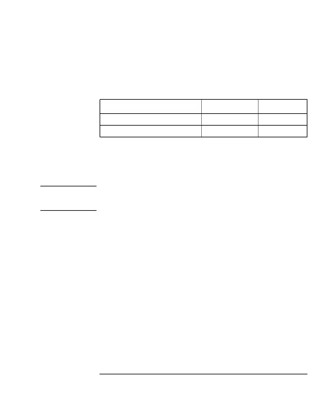
Table 4-2 shows some typical values for two types of slip-on connectors
for mainline cable:
Table 4-2 Typical L and C Values
For the connectors in Table 4-2, use of values within these ranges should
be optimum for the best corrected connector fault response and lowest
SRL spikes. Values far outside this range usually indicate a bad
calibration, a poor connector or connection, or a close-in cable fault which
cannot be compensated by the connector model.
NOTE The optimum calculated value for the connector lengths of “Gilbert Pogo”
connectors may be slightly negative. This is a normal value and should
not be a cause for concern.
For type-F connectors, which are typically used to measure 75 ohm drop
cable, the range of connector L and C values will vary widely and will
depend greatly on the quality of the type-F connector.
Connector L Value C Value
GTC-700-TX-GHZ-N (“GHz”) 40 to 80 mm 0 to 0.15 pF
GTC-700-TX-N (“Pogo”) −12 to 12 mm 0 to 0.125 pF
 Loading...


