7-38
Operating Concepts
Measurement Calibration
What Causes Measurement Errors?
Network analysis measurement errors can be separated into systematic, random, and drift
errors.
Correctable systematic errors are the repeatable errors that the system can measure.
These are errors due to mismatch and leakage in the test setup, isolation between the
reference and test signal paths, and system frequency response.
The system cannot measure and correct for the non-repeatable random and drift errors.
These errors affect both reflection and transmission measurements. Random errors are
measurement variations due to noise and connector repeatability. Drift errors include
frequency drift, temperature drift, and other physical changes in the test setup between
calibration and measurement.
The resulting measurement is the vector sum of the test device response plus all error
terms. The precise effect of each error term depends upon its magnitude and phase
relationship to the actual test device response.
In most high frequency measurements the systematic errors are the most significant
source of measurement uncertainty. Since each of these errors can be characterized, their
effects can be effectively removed to obtain a corrected value for the test device response.
For the purpose of vector accuracy enhancement, these uncertainties are quantified as
directivity, source match, load match, isolation (crosstalk), and frequency response
(tracking). The description of each of these systematic errors follows.
Random and drift errors cannot be precisely quantified, so they must be treated as
producing a cumulative uncertainty in the measured data.
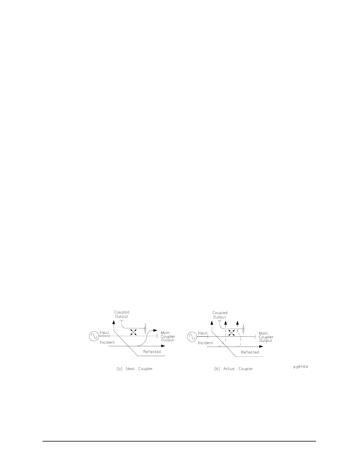
Directivity
Normally a device that can separate the reverse from the forward traveling waves (a
directional bridge or coupler) is used to detect the signal reflected from the test device.
Ideally the coupler would completely separate the incident and reflected signals, and only
the reflected signal would appear at the coupled output, as shown in Figure 7-21a.
Figure 7-21 Directivity

 Loading...


