7-41
Operating Concepts
Measurement Calibration
Frequency Response (Tracking)
This is the vector sum of all test setup variations in which magnitude and phase change as
a function of frequency. This includes variations contributed by signal-separation devices,
test cables, adapters, and variations between the reference and test signal paths. This
error is a factor in both transmission and reflection measurements.
For further explanation of systematic error terms and the way they are combined and
represented graphically in error models, refer to the “Characterizing Microwave
Systematic Errors” on page 7-41.
Characterizing Microwave Systematic Errors
One-Port Error Model
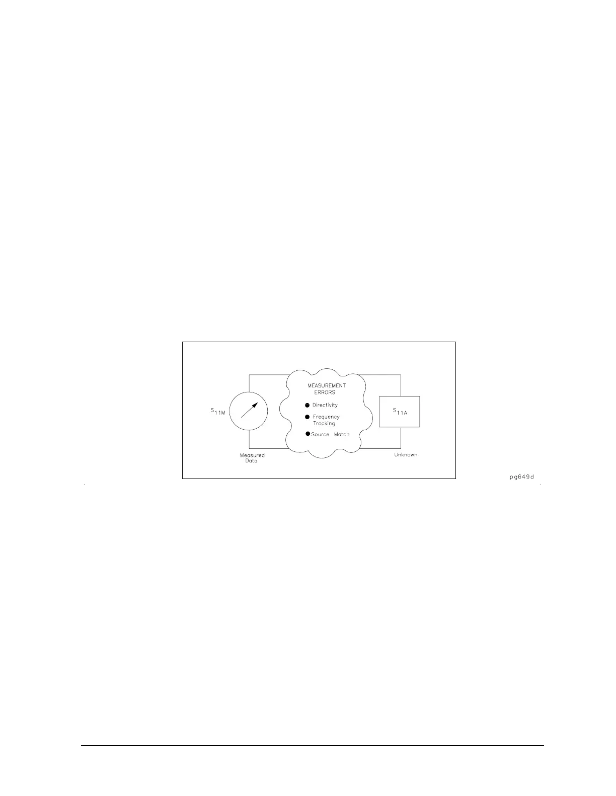
In a measurement of the reflection coefficient (magnitude and phase) of a test device, the
measured data differs from the actual, no matter how carefully the measurement is made.
Directivity, source match, and reflection signal path frequency response (tracking) are the
major sources of error. See Figure 7-24.
Figure 7-24 Sources of Error in a Reflection Measurement

 Loading...


