1-8
Supplement for the User’s Guide (Firmware Version 7.66)
Using Ripple Limits to Test a Device
Setting Up the Analyzer to Perform the Ripple Test
This section sets up the analyzer so that a bandpass filter can be easily viewed on the
analyzer display.
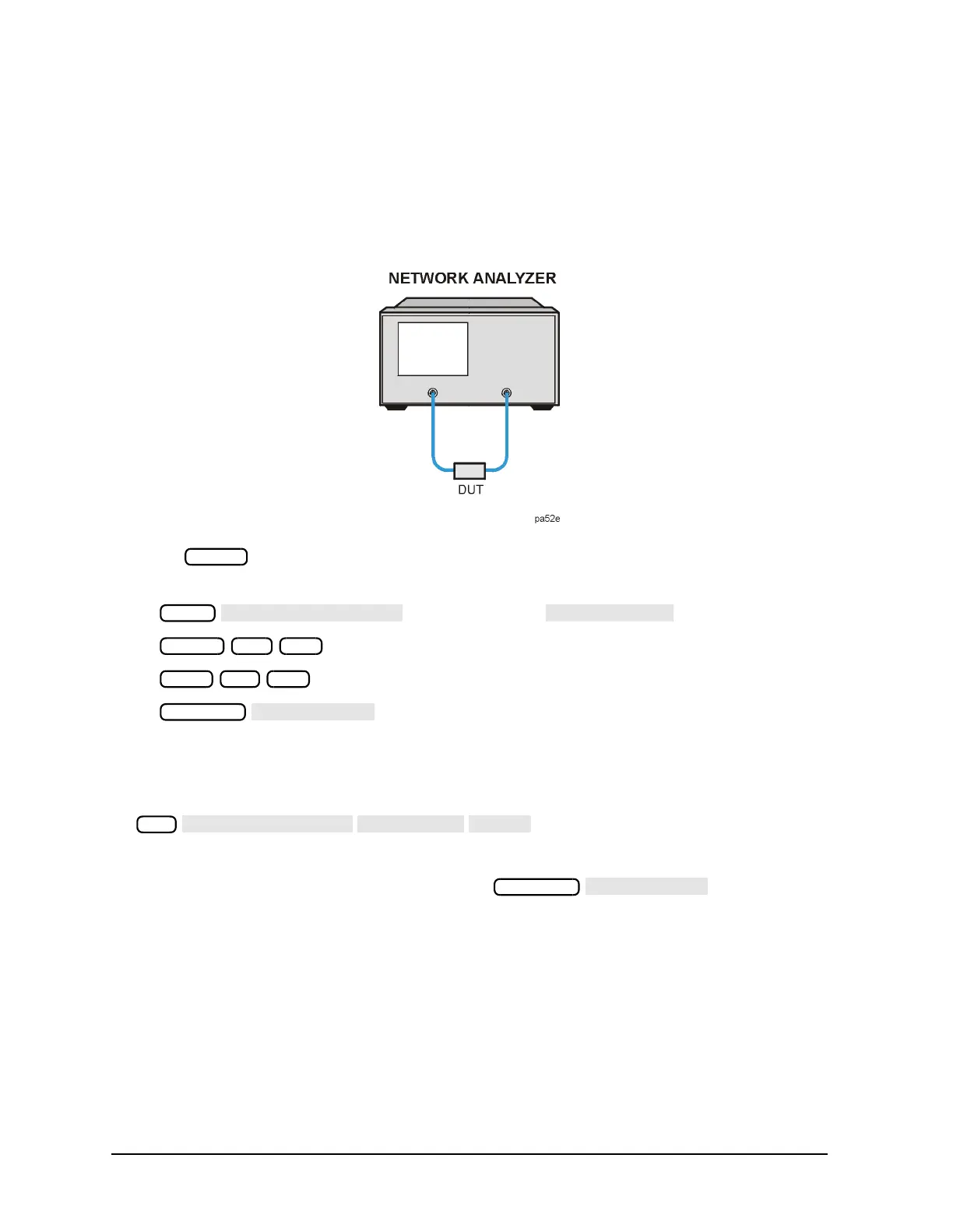
1. Connect your filter as shown in Figure 1-2.
Figure 1-2 Connections for an Example Ripple Test Measurement
2. Press and choose the measurement settings. For this example, the
measurement settings are as follows:
• or on ET models:
•
•
•
You may also want to select settings for the number of data points, power, averaging,
and IF bandwidth.
3. Substitute a thru for the device and perform a response calibration by pressing:
4. Reconnect your test device.
5. To better view the measurement trace, press . Refer to
Figure 1-3.
Preset
Meas
Center 1.8 G/n
Span 3.4 G/n
Scale Ref
Cal
Scale Ref

 Loading...


