Agilent MOI for DisplayPort Cable & Connector Compliance Tests
21
5.5.4.3. Data Analysis
Read Pass/Fail signs on Trace 3. (item 2 in Figure 5-4).
5.5.5. Inter- pair Skew
Measurement
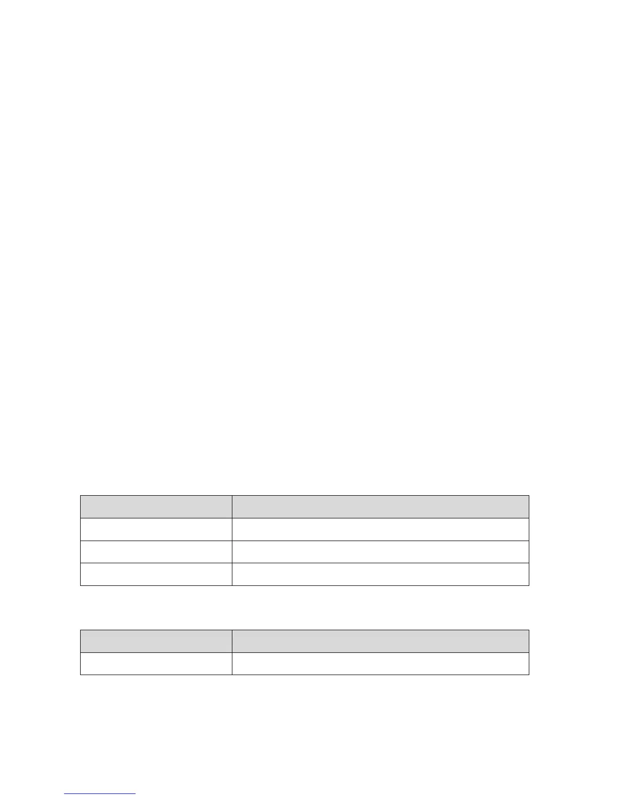
1. Connect the test fixture to the test cables according to Table 5-3. Unused test ports
should be terminated.
2. Connect Display Port cable to the test fixture.
3. Press Channel Next key to select Channel 1.
4. Press Channel Max key to enlarge Channel 1.
5. Click Stop Single for Time Domain measurement.
6. Read the propagation delay (item 3 in Figure 5-3), and write it down.
7. Repeat step 1 to step 6 for every channel.
5.5.5.1. Data Analysis
Find the maximum and minimum value among the measured propagation delay. Then,
Inter-pair Skew = Absolute(maximum value – minimum value)
Inter-pair Skew Upper Limit for High Bit Rate Cable Assembly

 Loading...


