52 Chapter 3
Making Fault Location Measurements
Basic Measurement Procedures
Calibrate the Analyzer
When practical, a calibration should be done at the measurement reference plane
using open, short, and load calibration standards to correct the instrument and
optimize accuracy. For calibration procedures, see the analyzer’s “User’s Guide”.
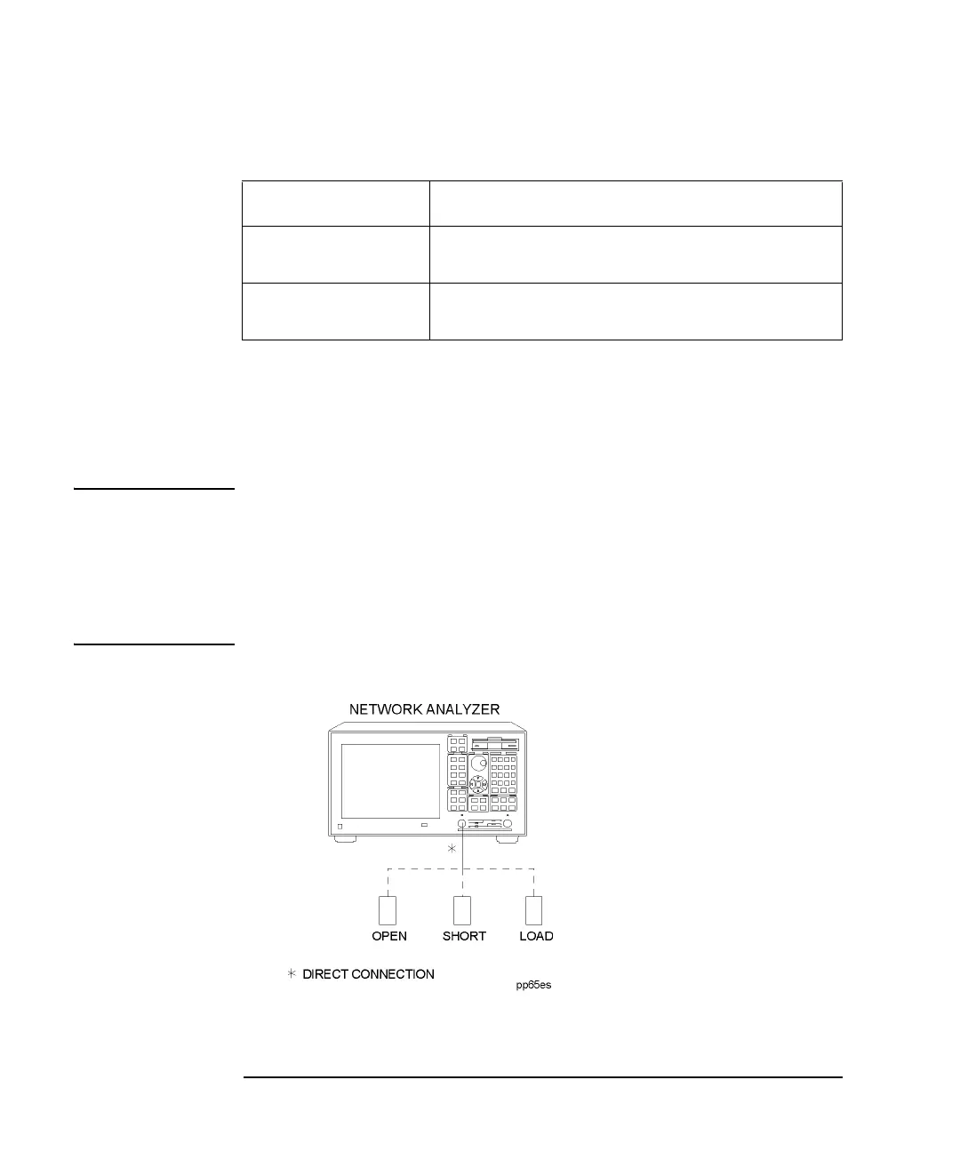
NOTE Most fault location measurements are made by connecting the cable under test
directly to the analyzer's Port 1 test port. In this case the measurement reference
plane would be the analyzer's port and you would connect calibration standards to
the test port as shown in
Figure 3-4. Fault location measurements may also be made
using a test lead cable. If this is the case, the measurement reference plane would be
the end of the test lead cable, and calibration standards would be connected to the
end of the test lead cable.
Figure 3-4 Calibrate the Instrument
Keystroke Function
One Way Sets the values displayed on the horizontal axis to
one-way.
Round Trip Sets the values displayed on the horizontal axis to
round-trip.
 Loading...


