Chapter 4 65
Making SRL Measurements
How to Make SRL Measurements
Connect the Cable Under Test
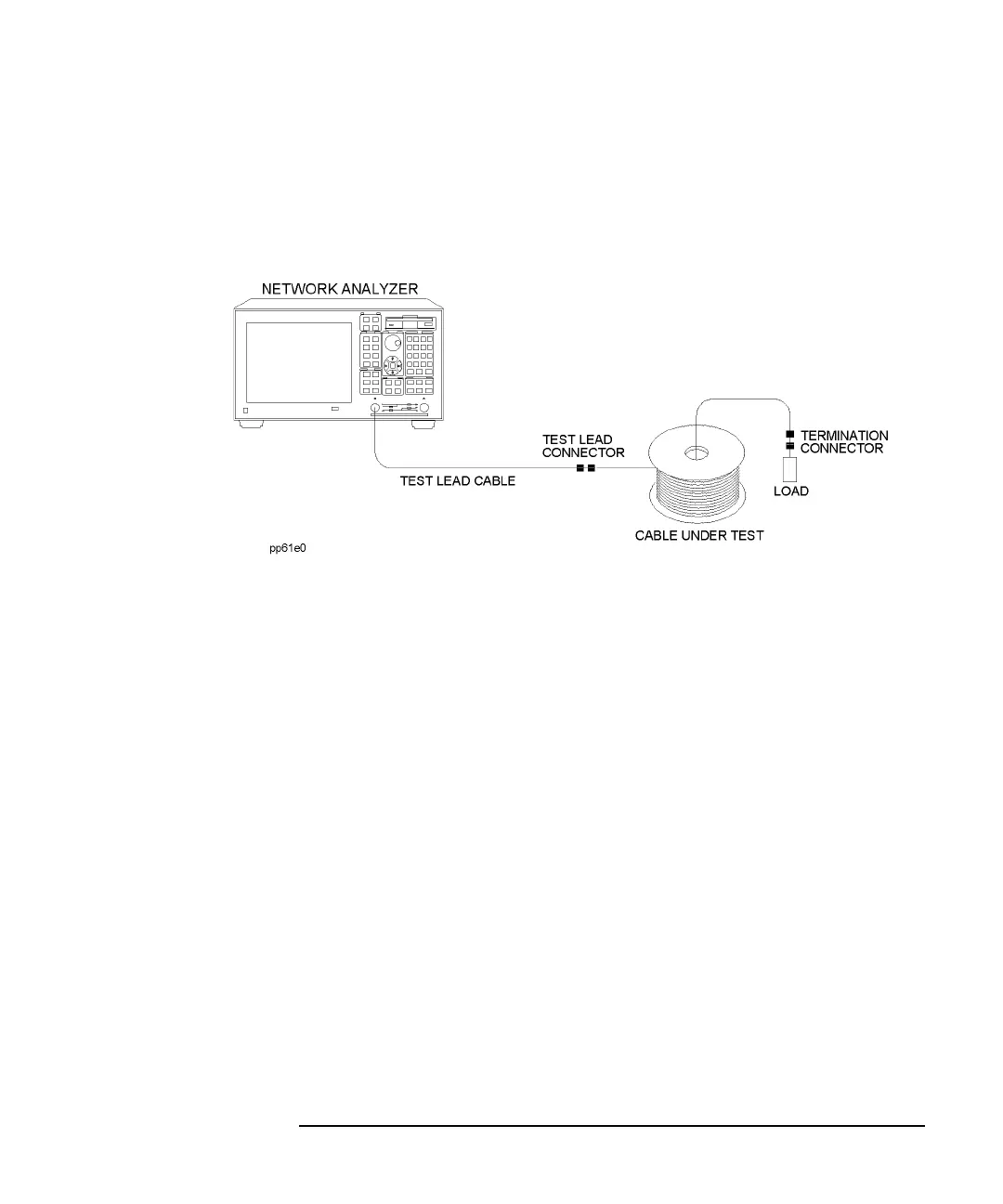
The basic equipment setup for SRL measurements is illustrated in Figure 4-3.
Figure 4-3 Basic SRL Measurement Setup
Determine the Connector Model
After connecting the cable under test as shown in Figure 4-3, you should determine
the connector model for the best response. The connector model may need to be
determined each time a new cable is tested.
When using connectors that have very consistent interfaces, modeling the connector
for each new connection to a cable may not be required. When using connectors that
do not have a repeatable interface contact, modeling the connector for each new
connection to a cable is necessary.
For some SRL measurements, the response of the connector can be critical for
obtaining a true measurement of structural return loss. For example, a connector
with a return loss of 30 dB will swamp out SRL responses less than about -20 dB. A
connector with a 40 dB return loss will provide a more accurate measurement of the
-20 dB responses.
Table 4-1 shows the effects of a connector mismatch on the measurement of a -35
dB SRL spike.

 Loading...


