64 Chapter 4
Making SRL Measurements
How to Make SRL Measurements
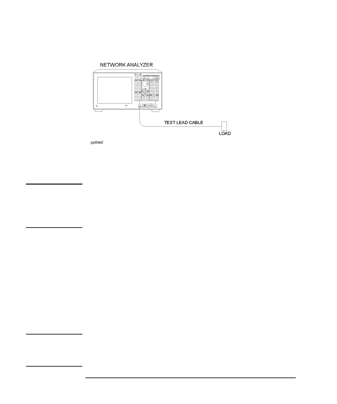
Figure 4-2 Connect the Load
2. Observe the magnitude of the response on measurement channel 1. The highest
peak response on channel 1 is the system directivity. If the peak response on
channel 1 is <-50 dB, the calibration is good. If the peak response is >-40 dB,
you should recalibrate the analyzer.
NOTE Measurement quality is related to system directivity. For the highest quality
measurements, system directivity should be <-50 dB, but measurement quality is
acceptable up to -40 dB. See
“SRL Measurement Uncertainty vs System
Directivity” on page 88.
Also see “Measurement Uncertainties” on page 25.
Determine the Quality of the Test Lead Cable.
1. Leave the load connected to the end of the test lead cable and note the level of
the peak response on measurement channel 1 (the system directivity).
2. Wiggle the test lead cable while observing the response on the analyzer's
display.
a. If the measurement trace is relatively stable, the test lead cable is of good
quality.
b. If you observe significant movement in the peaks of the measurement trace
when wiggling the cable (>10 dB), the test lead cable may need to be
replaced.
NOTE Variation in the system directivity that occurs as a result of test lead cable movement
degrades the quality and repeatability of SRL measurements. Take precautions to
protect your test lead cables from mishandling or abuse. Do not step on or drive
vehicles over test lead cables.
 Loading...


