10 Chapter 1
Introduction and Measurement Theory
Fault Location Measurement Theory
Fault Location Measurement Theory
This section describes basic fault location measurement theory, how the analyzer
converts frequency-domain data to distance-domain data, and the relationship
between start distance, stop distance and frequency span.
Fault location measurements are designed to quickly and easily locate faults, or
discontinuities, in either 50 ohm or 75 ohm transmission lines. Refer to
Figure 1-1
for the following discussion.
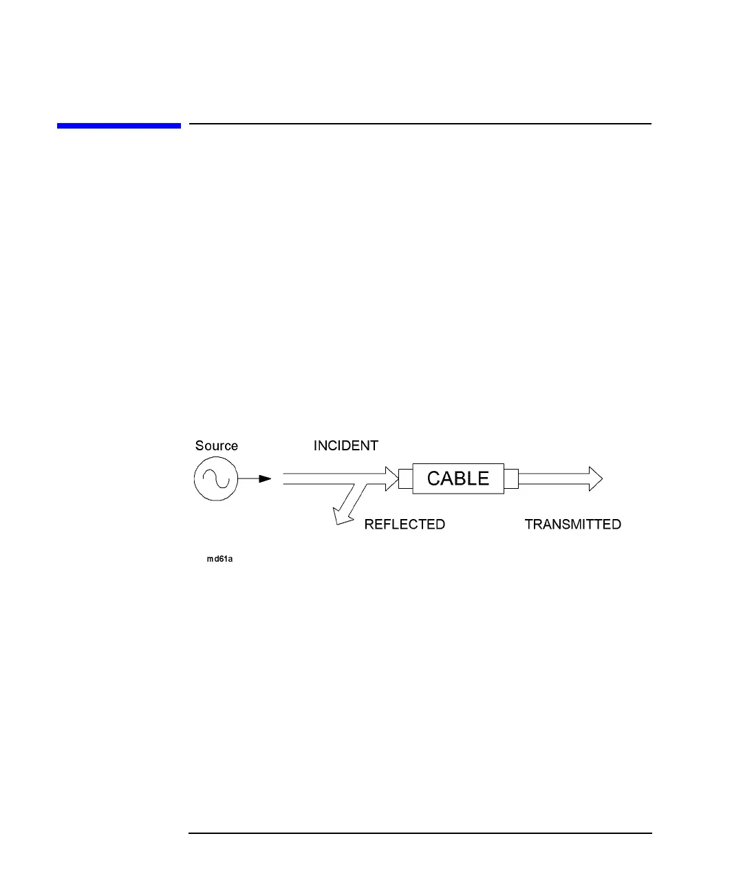
The network analyzer has an RF signal source that produces an incident signal that
is used as a stimulus to locate and measure discontinuities in your transmission line
or cable. Each fault or discontinuity responds by reflecting a portion of the incident
signal and transmitting the remaining signal.
The analyzer measures the frequency response of the cable and then transforms the
frequency data to distance data.
Figure 1-1 Fault Response to an RF Signal
 Loading...


