Chapter 7 87
Characteristics
General Performance Characteristics
General Performance Characteristics
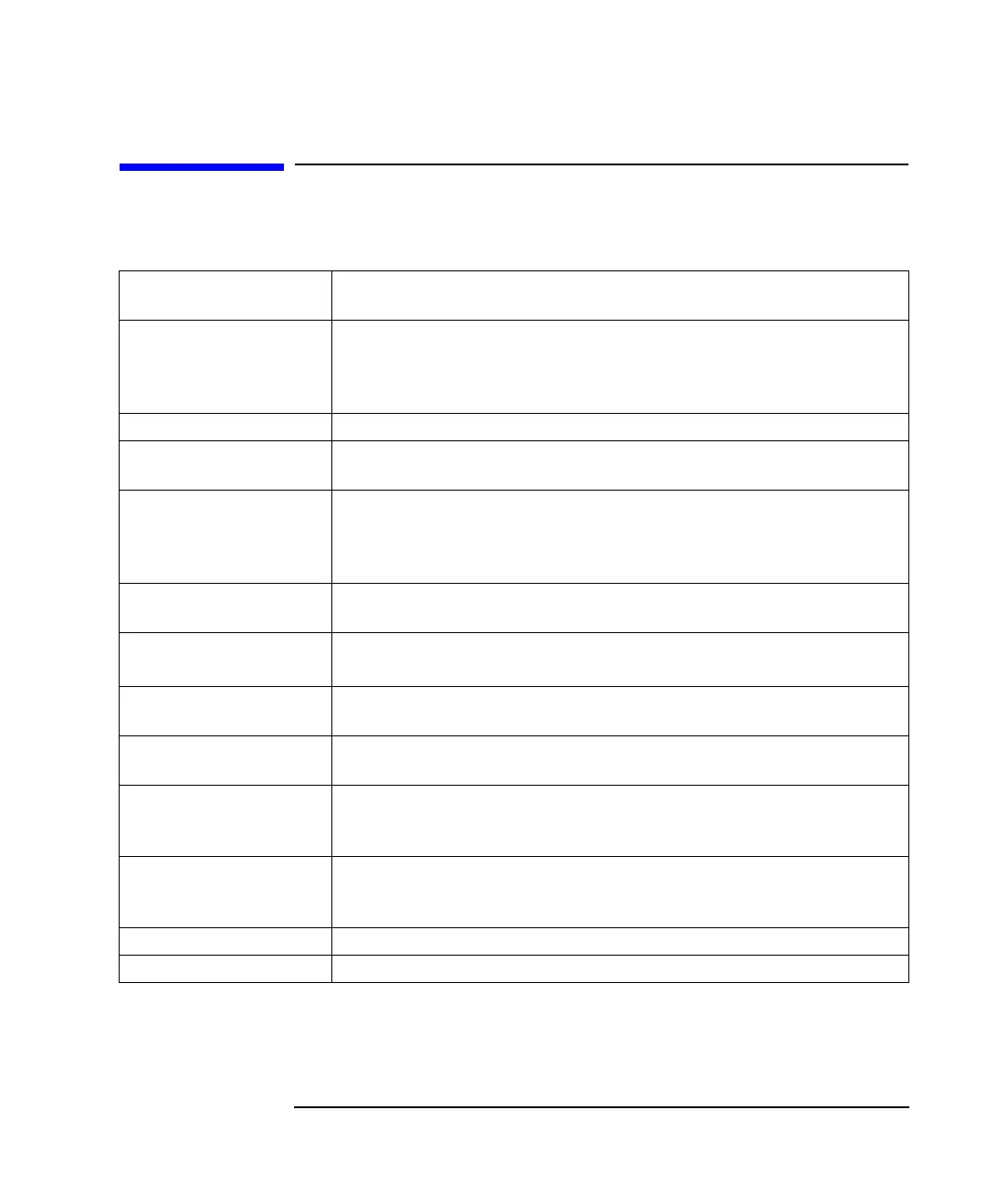
SRL Measurement
Mode
Structural Return Loss
Fault Location
Measurement Mode
Return loss (dB) versus distance
Reflection coefficient magnitude versus distance
SWR versus distance
Dynamic Range 40 dB (based on system directivity after calibration)
Windowing Minimum, medium and maximum windows are available for optimizing
distance response data
Amplitude Accuracy
1
±2.5 dB typical (minimum windowing)
±1.2 dB typical (medium windowing)
±0.4 dB typical (maximum windowing)
Data Correction Data is normalized to the open/short/load response at the output port. Data
correction for line losses and preceding mismatches is also available.
Measurement and Data
Storage
2
Use the internal disks to store and recall setups and data.
Markers Ten independently controlled markers can be used to display return loss,
reflection coefficient, SWR, or impedance versus distance.
Limit Lines Limit lines may be entered for comparison to specification limits and
pass/fail testing.
Remote Programming The analyzer can be controlled from an external computer through the IEEE
488.2 GPIB port or the LAN interface. Use standard SCPI program
subsystem commands to control the analyzer.
Hard Copy
2
The analyzer can be configured to output print data to the parallel port, the
USB port, or to a file. The data can be either a graph or a tabular listing of
data points.
Fault Range Up to 10000.00 meters. (See Table 7-10 and Table 7-11.)
Resolution Down to 0.195% of range. (See Table 7-10 and Table 7-11.)
1. Inaccurate cable loss factor and/or multiple fault correction may introduce additional error
uncertainties.
2. See your analyzer's User's Guide for information.
 Loading...


