66 Chapter 4
Making SRL Measurements
How to Make SRL Measurements
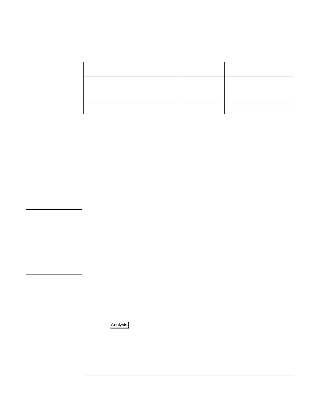
Table 4-1 Measurement Results with Varying Connector Mismatches
As indicated by Table 4-1, the best true SRL measurement is made when the
contribution of the connector is minimized by
• a good calibration
• a high-quality connector and connection (see Chapter 2, "Cable Preparation")
• a connector model which provides the lowest corrected connector response
The effects of the connector response can be minimized with the built-in connector
model and the corrected connector response can be measured while the SRL
measurement is being made. For some connectors, a response correction of up to 15
dB or more improvement is possible with the built-in connector model.
NOTE The maximum extent to which the effects of the connector response can be removed
is to the accuracy and repeatability of the analyzer system (including the effects of
test lead cable stability and quality). The accuracy of the system is given by the
system directivity of the analyzer (which can be determined from the trace with a
load connected after calibration).
For determining measurement uncertainty, use the value of the system directivity
and the connector response. See
“SRL Measurement Uncertainty vs Connector
Fault” on page 92.
Connector Model for Long Cables
If a long cable is being measured, you can use the “Measure Connector” feature to
automatically determine the L and C values. (A long cable is defined as
approximately 300 m (1000 ft)).
3. Press - SRL to display the "SRL" menu.
4. Press Portx Connector (x is the port to which the cable is connected).
5. Connect the terminated cable, then press Measure Connector to set the L and C
values automatically
.
Corrected Connector Return Loss SRL Total Measured
-53 dB -35 dB -34 dB
-42 dB -35 dB -31.8 dB
-35 dB -35 dB -29 dB
 Loading...


