5-4
Post-Repair Procedures
Adjustments
Adjustments
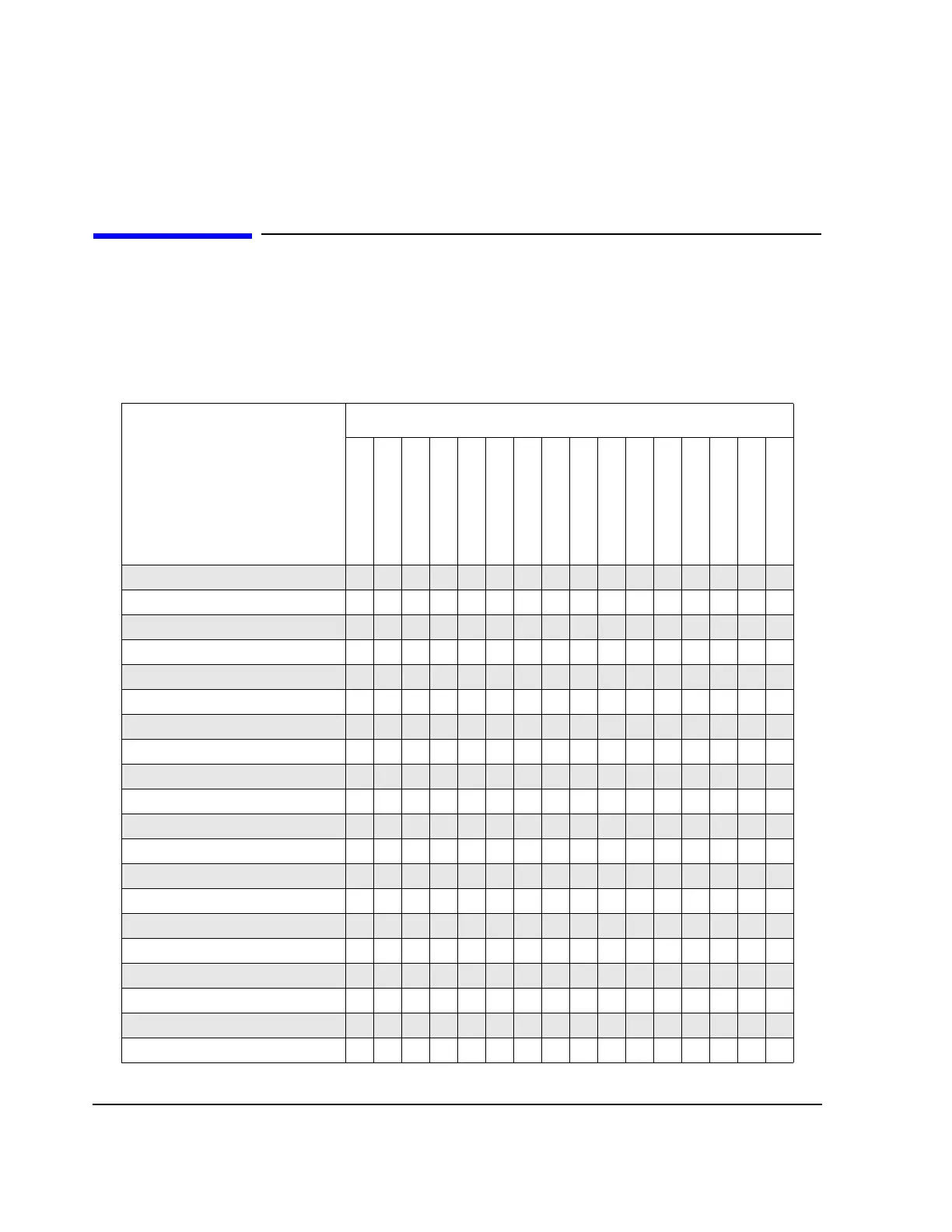
The following matrix shows you which adjustments must be performed when a specific assembly is
repaired or replaced. Except where noted, all adjustments are automated using software. Refer to the “HP
ESG-D Series Signal Generators Calibration Guide” for more information on adjustments.
Adjustments
Adjustments
Repaired/Replaced Assembly
A1 Front Panel Bd
A2 Display
A2DS1 Lamp
A3 Inverter
A4 Power Supply
A7 Baseband Gen Bd
A8 Data Gen Bd
A9 Output Bd
A11 Reference Bd
A12 Synthesizer Bd
A14 Motherboard
A14BT1 Battery
A15 Daughterboard
A16 Line Module
A17 Rear Panel Bd
AT1 Attenuator
ABUS ADC Cal ● ●
Internal Source Cal ● ● ●
VCO Bias Adjustment ● ● ●
Lock Angle Adjustment ● ● ●
Kv vs Frequency Cal ● ● ●
AM Audio Path Offset ● ● ● ●
Timebase DAC Cal ● ● ●
FM Scale DAC Offset Cal ● ● ● ●
FM Path Offset Cal ● ● ● ●
FM In-band DAC Offset Cal ● ● ● ●
FM Invert Amp Offset Cal ● ● ● ●
FM1/2 Path Ratio Gain Cal ● ● ● ●
Mod Source Relative Gain Cal ● ● ● ●
FM Delay Pot Adjustment ● ● ● ●
Wide BW PM Cal ● ● ● ●
DCFM Cal ● ● ● ● ●
Peak Detector Cal ● ● ● ●
Normal Mode PM Cal ● ● ● ●
Burst Modulator Cal ● ● ●
FM Out-of Band Cal ● ● ● ●

 Loading...


