256 Agilent InfinityLab LC Series 1260 Infinity II FLD User Manual
12
Hardware Information
Interfaces
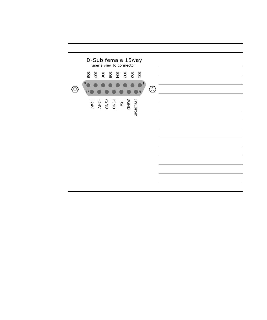
IO (Input/Output) Lines
• Eight generic bi-directional channels (input or output).
• Same as the APG Remote.
• Devices like valves, relays, ADCs, DACs, controllers can be
supported/controlled.
1-Wire Data (Future Use)
This serial line can be used to read out an EPROM or write into an EPROM of a
connected ERI-device. The firmware can detect the connected type of device
automatically and update information in the device (if required).
Pin Enhanced Remote
1IO 1 (START
REQUEST)
2IO 2 (STOP)
3IO 3 (READY)
4 IO 4 (POWER ON)
5 IO 5 (NOT USED)
6IO 6 (SHUT DOWN)
7IO 7 (START)
8 IO 8 (PREPARE)
91 wire DATA
10 DGND
11 +5 V ERI out
12 PGND
13 PGND
14 +24 V ERI out
15 +24 V ERI out
 Loading...