Chapter 6: Replacing Assemblies
To remove and replace the probe power and control board
110
6
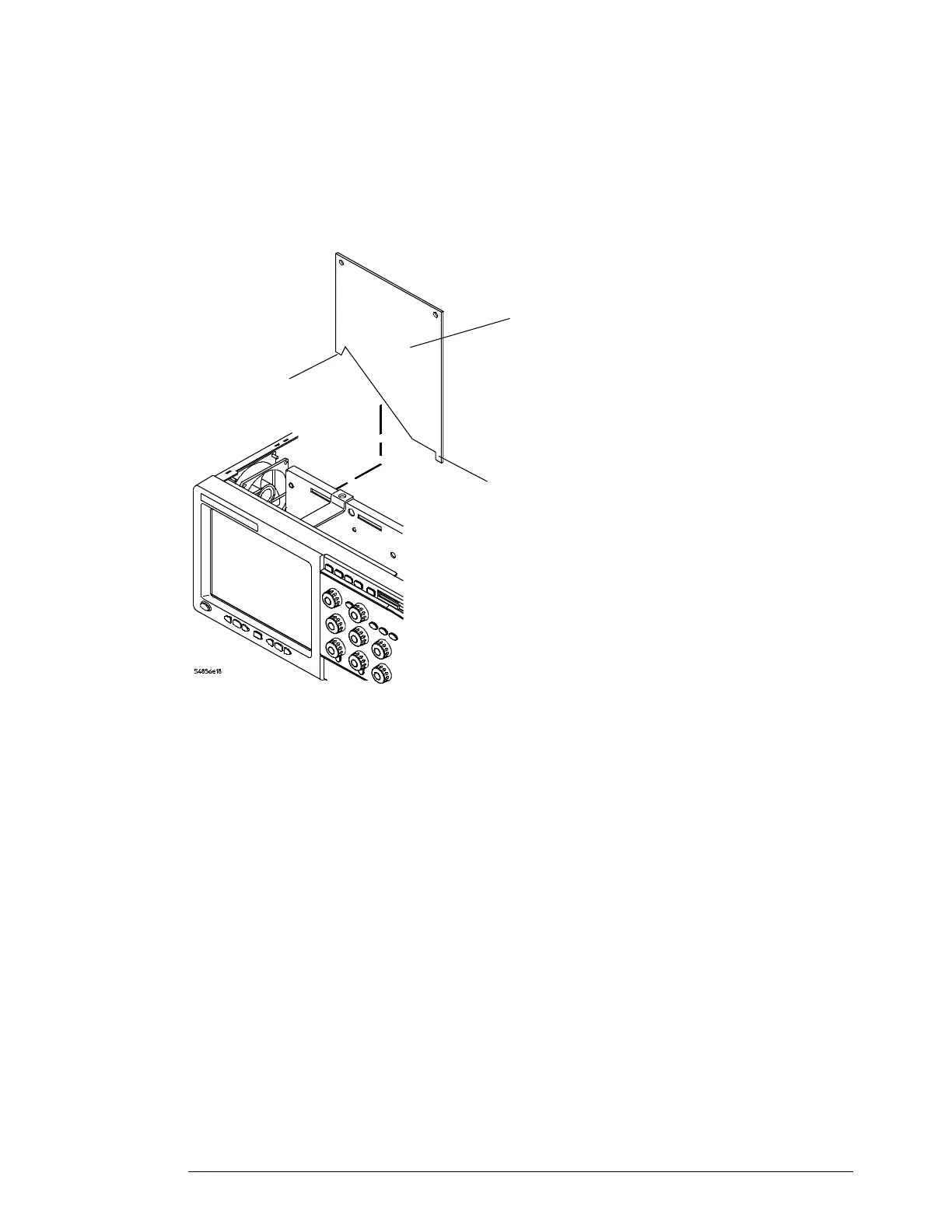
To replace the probe power and control assembly, reverse the above procedure.
When inserting the assembly, be sure the two tabs on the circuit board engage the two slots in
the sheet metal. Also, be sure to carefully lock in the connector for the mylar flex cable when
reattaching the cable. See “To disconnect and connect Mylar flex cables” on page 106.
Figure 6-8
Probe power and control assembly
Tab
Tab
Probe Power and
Control Board

 Loading...


