Chapter 6: Replacing Assemblies
To remove and replace the covers
104
To remove and replace the covers
Use this procedure to remove and replace the covers. When necessary, refer to other removal
procedures. The graphics in this chapter are representative of the oscilloscope at the time of this
printing. Your unit may look different.
1
Disconnect the power cable.
2 Disconnect all oscilloscope probes and BNC input cables from the front panel.
3 Disconnect any other cables, such as mouse, keyboard, printer, or GPIB cables.
4 Remove the two Torx T20 screws securing the side handle.
5 Remove the four Torx T20 screws that secure the rear feet (two in each foot).
6 Remove the four Torx T20 screws that secure the top sleeve to the chassis.
If removing the bottom cover only, you do not need to remove these four screws.
7
Remove the four Torx T20 screws that secure the bottom cover to the chassis.
If removing the top sleeve only, you do not need to remove these four screws.
8
Place the unit so the bottom is facing up.
9 Remove the eight Torx T10 screws that secure the top and bottom covers to the chassis.
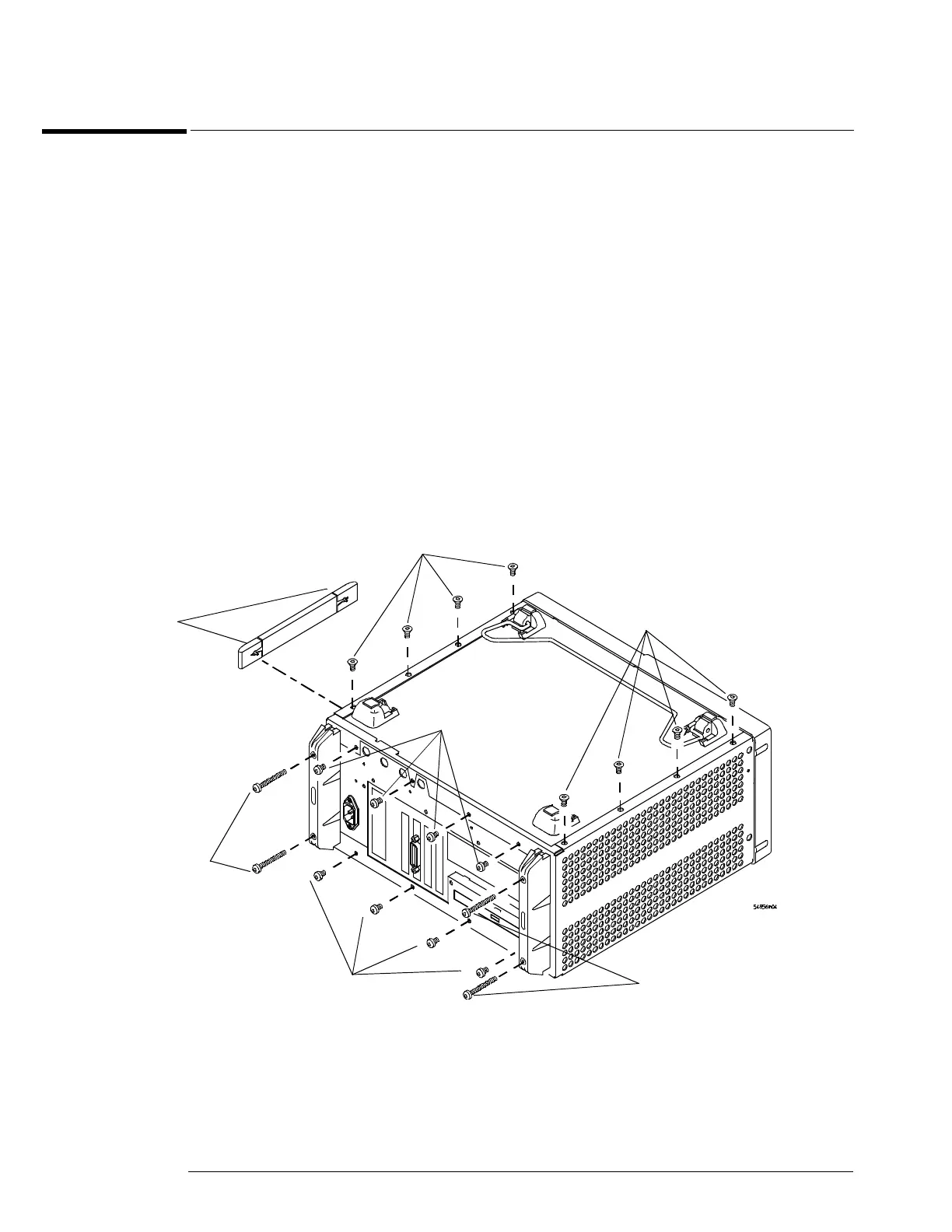
Figure 6-1
Fasteners to remove handle, rear feet, and covers
2 Handle
Screws
(Torx T20)
Torx
T10
Torx
T20
Torx
T10
Torx
T20
Torx
T20
Torx
T20

 Loading...


