Chapter 2: Setting Up the Oscilloscope
To verify basic oscilloscope operation
30
To verify basic oscilloscope operation
1 Connect an oscilloscope probe to channel 1.
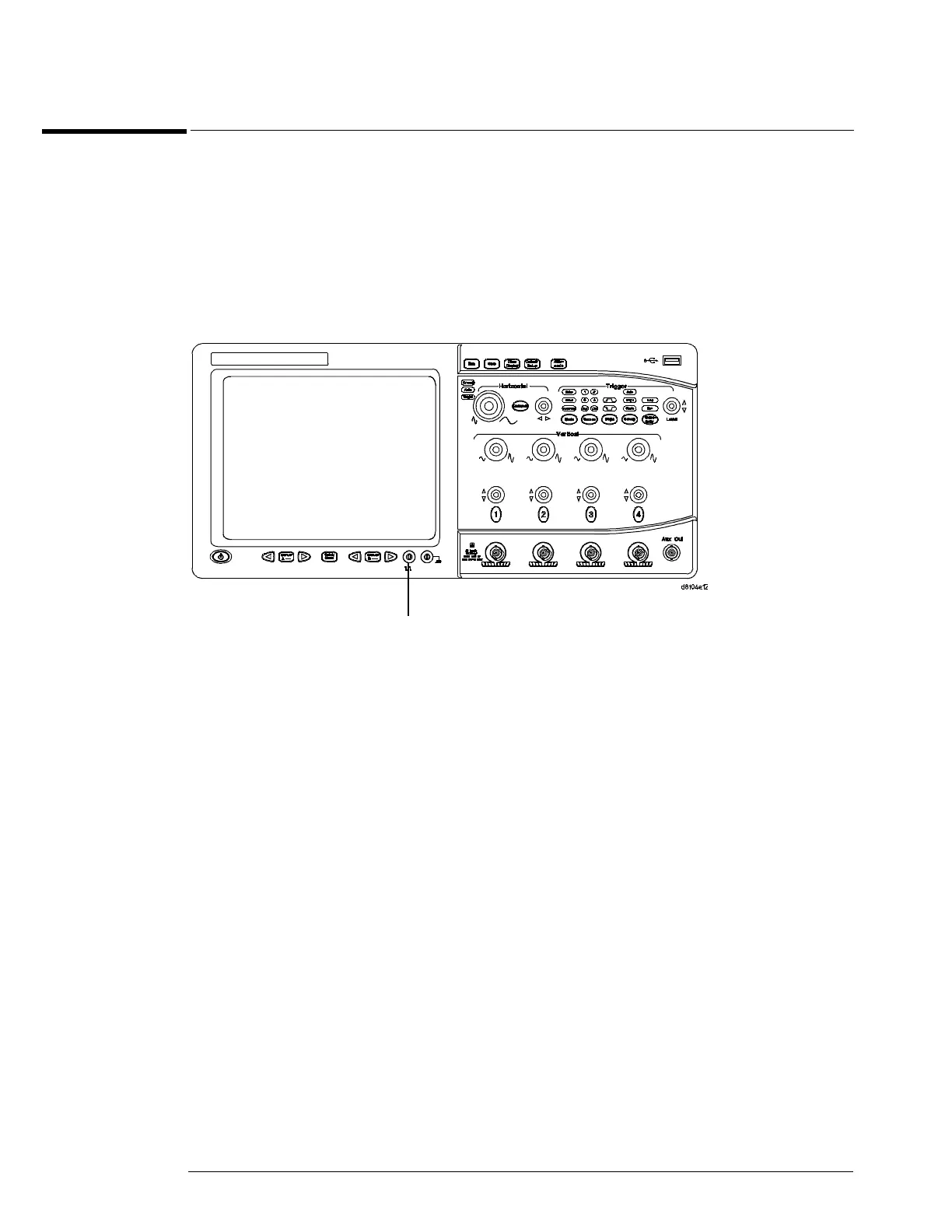
2 Attach the probe to the probe compensation output on the front panel of the
oscilloscope.
Use a probe grabber tip so you do not need to hold the probe. The probe compensation output
is marked with a square wave symbol.
Figure 2-12
Verifying Basic Oscilloscope Operation
3 Press the Default Setup key on the front panel.
The display will pause momentarily while the oscilloscope is configured to its default settings.
4
Press the Autoscale key on the front panel.
The display will pause momentarily while the oscilloscope adjusts the sweep speed and vertical
scale. You should then see a square wave with an amplitude of approximately 1.1 Vpp at about
700 to 800 Hz. If you do not see the waveform, ensure your power source is adequate, the
oscilloscope is powered-on, and the probe is connected securely to the front-panel channel input
BNC and to the probe calibration output.
5
Move the mouse around the mouse surface and verify that the on-screen mouse pointer
coincides with the mouse movement.
Calibration
Output

 Loading...


