Chapter 6: Replacing Assemblies
To remove and replace the backlight inverter board
111
To remove and replace the backlight inverter board
Use this procedure to remove and replace the backlight inverter board. When necessary, refer
to other removal procedures. The graphics in this chapter are representative of the oscilloscope
at the time of this printing. Your unit may look different.
WARNING SHOCK HAZARD!
The backlight inverter assembly, which is mounted at the front corner of the oscilloscope near
the flat-panel display, operates at high voltages from 300-1 kVAC
rms
. DO NOT handle this
assembly while it is in operation.
1
Disconnect the power cable and remove the top and bottom covers.
2 Disconnect the two backlight cables from the top of the backlight inverter board.
3 Disconnect the backlight primary cable from the bottom of the backlight inverter
board.
4 Using a long Torx T10 driver, remove the two Torx T10 screws that secure the backlight
inverter board to the chassis.
5 Lift the backlight inverter board out through the top of the chassis.
6 To replace the backlight inverter board, reverse this procedure.
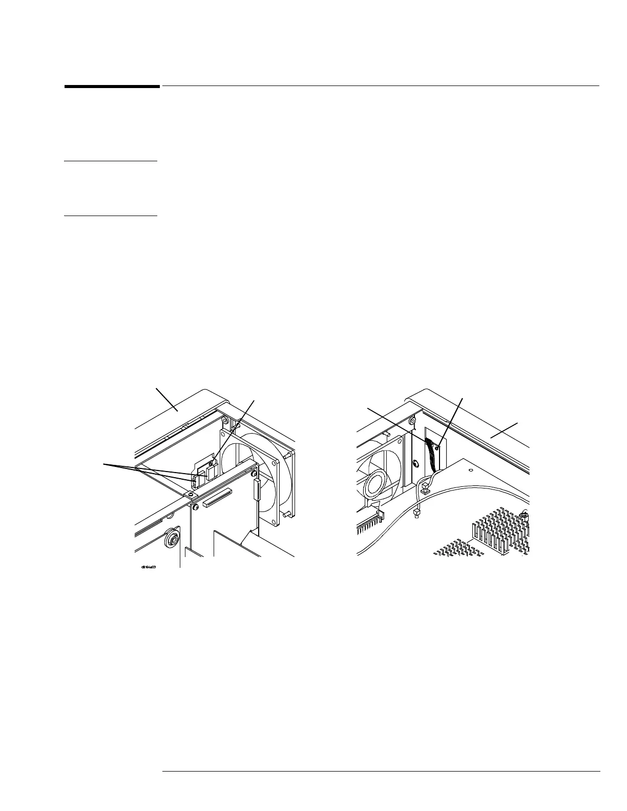
Figure 6-9
Removing the backlight inverter board
Backlight
inverter
cable
LCD power
cables
Bottom edge
front panel
Top edge
front panel
T10 torx screw
T10 torx
screw
Top View Bottom View

 Loading...


