Chapter 6: Replacing Assemblies
To remove and replace the display board
125
To remove and replace the display board
Use this procedure to remove and replace the display board. When necessary, refer to other
removal procedures. The graphics in this chapter are representative of the oscilloscope at the
time of this printing. Your unit may look different.
1
Disconnect the power cable and remove the top cover.
2 Disconnect these cables from the display board:
• Backlight primary cable
• Flat-panel display driver multi-colored cable
3
Remove the Torx T10 screw that secures the display board to the chassis.
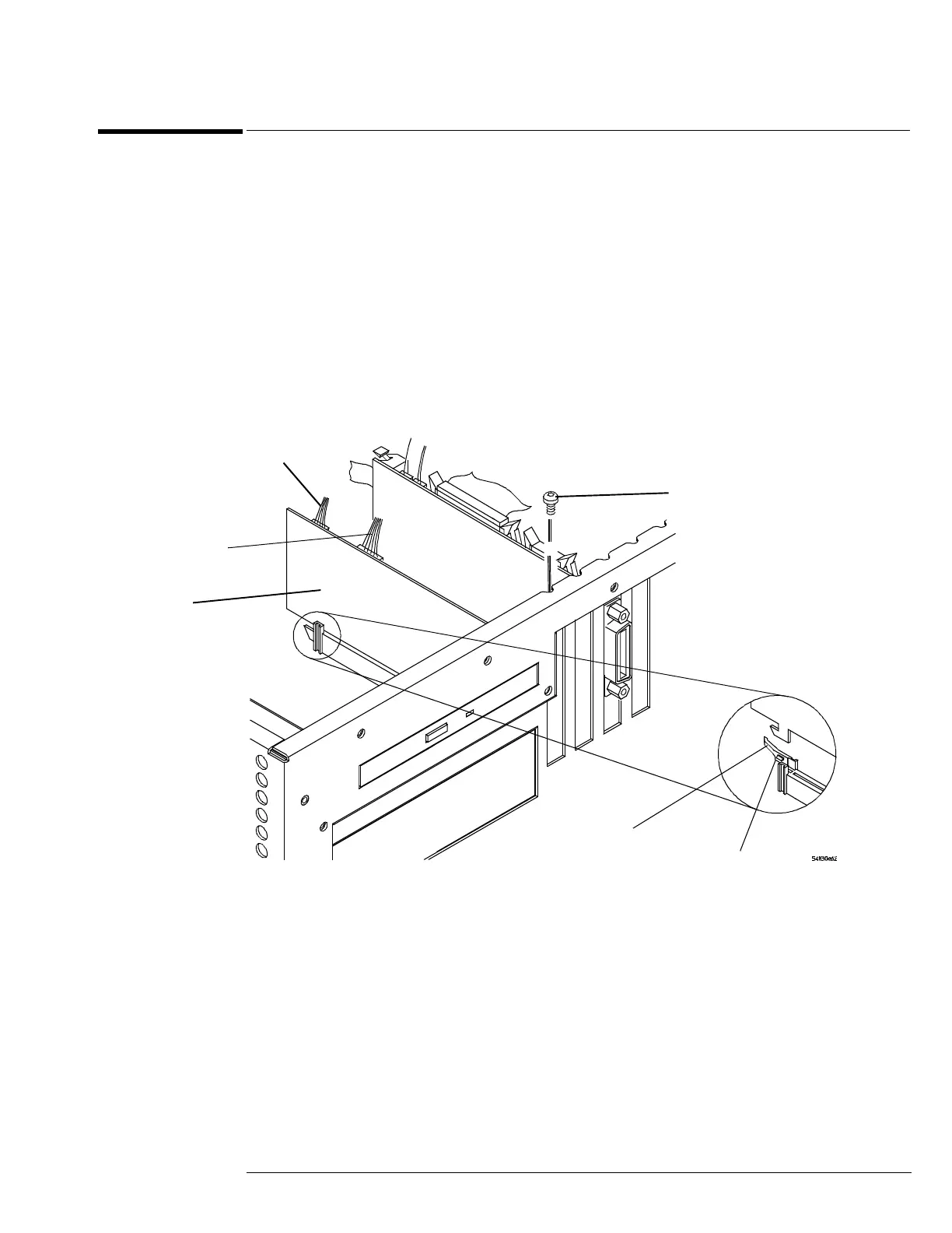
Figure 6-23
Removing the display board
4 While pulling connector’s lever back to release the latch, grasp the board at the top
corners and pull it straight up until it is free of the card cage.
5 To replace the board, reverse the above procedure.
Be sure to observe correct polarity on all cables when replacing the board.
Backlight primary cable
Flat-panel display
driver multi-colored
cable
Display board
T10 Torx Screw
Connector lever
Snap latch

 Loading...


