Chapter 6: Replacing Assemblies
To remove and replace the motherboard
130
To remove and replace the motherboard
Use this procedure to remove and replace the motherboard assembly. When necessary, refer to
other removal procedures. The graphics in this chapter are representative of the oscilloscope at
the time of this printing. Your unit may look different.
CAUTION REPLACE MOTHERBOARD WITH THE SAME TYPE!
Be sure to order the correct motherboard, and replace the motherboard with the same type.
1
Disconnect the power cable and remove the top cover.
2 Remove the CD-ROM drive (see page 128).
3 Remove all cables from the PCI cards.
4 Remove all PCI cards from the motherboard.
5 Disconnect all cables from the motherboard.
Note that the connectors marked ‘A’ below require removal of the silicone, using a sharp
instrument, before disconnecting. When reconnecting, use enough Loctite 5145 or equivalent
RTV silicone to secure the connectors to the headers and the motherboard. (See Figure 6-14.)
6
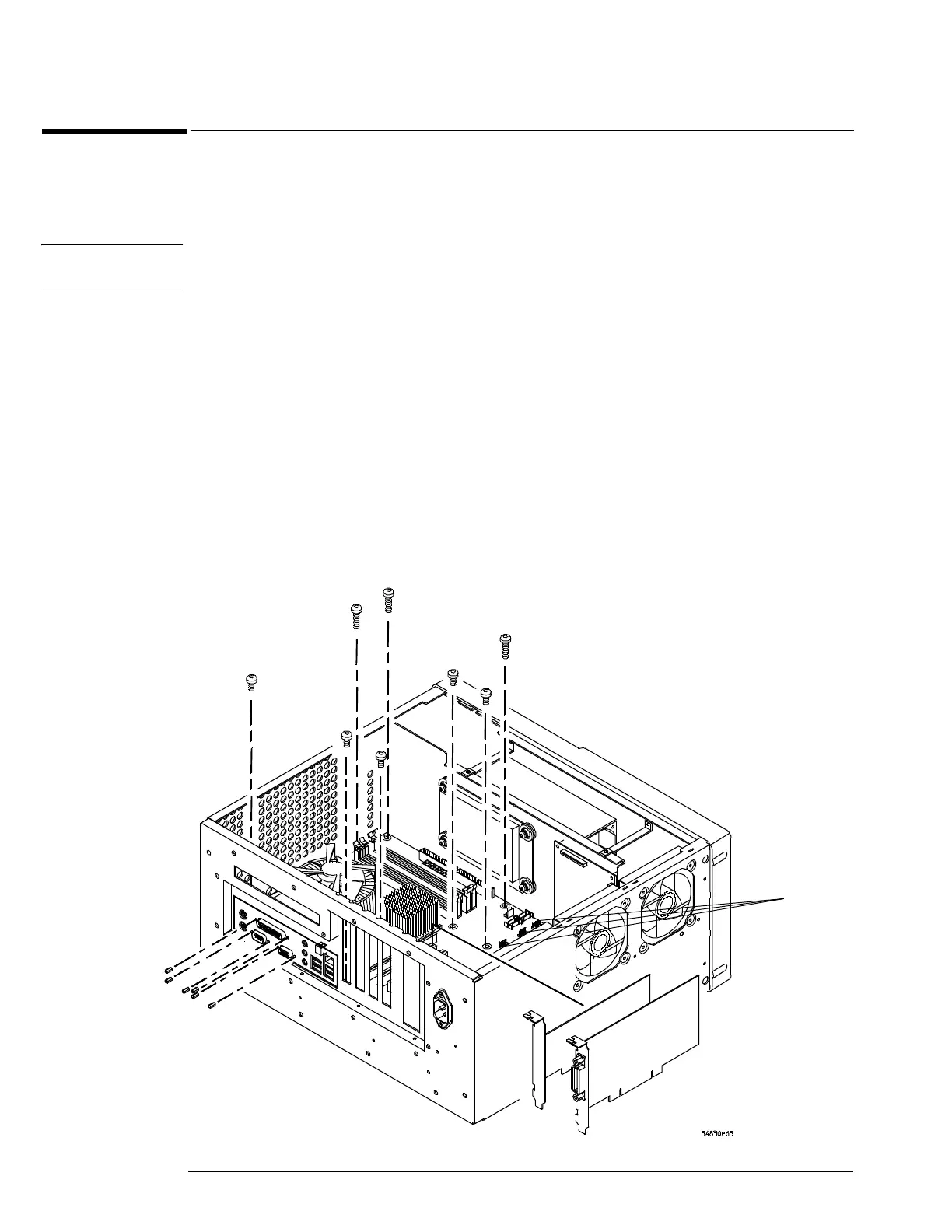
Remove the six 5 mm port lock screws from the rear panel connectors.
7 Remove the 5 short and 3 long Torx T10 screws holding the motherboard to the ATX
tray.
Figure 6-28
Removing the motherboard
Port lock
screws (6)
Torx T10
screws (8)
PCI cards
A

 Loading...


