Chapter 6: Replacing Assemblies
To remove and replace the probe power and control board
109
To remove and replace the probe power and control board
Use this procedure to remove and replace the probe power and control board. When necessary,
refer to other removal procedures. The graphics in this chapter are representative of the
oscilloscope at the time of this printing. Your unit may look different.
1
Disconnect the power cable and remove the top cover.
2 Disconnect the AutoProbe interface cable.
The connector must be unlocked before you can remove the flex cable. See “To disconnect and
connect Mylar flex cables” on page 106..
3
Disconnect the probe power cable.
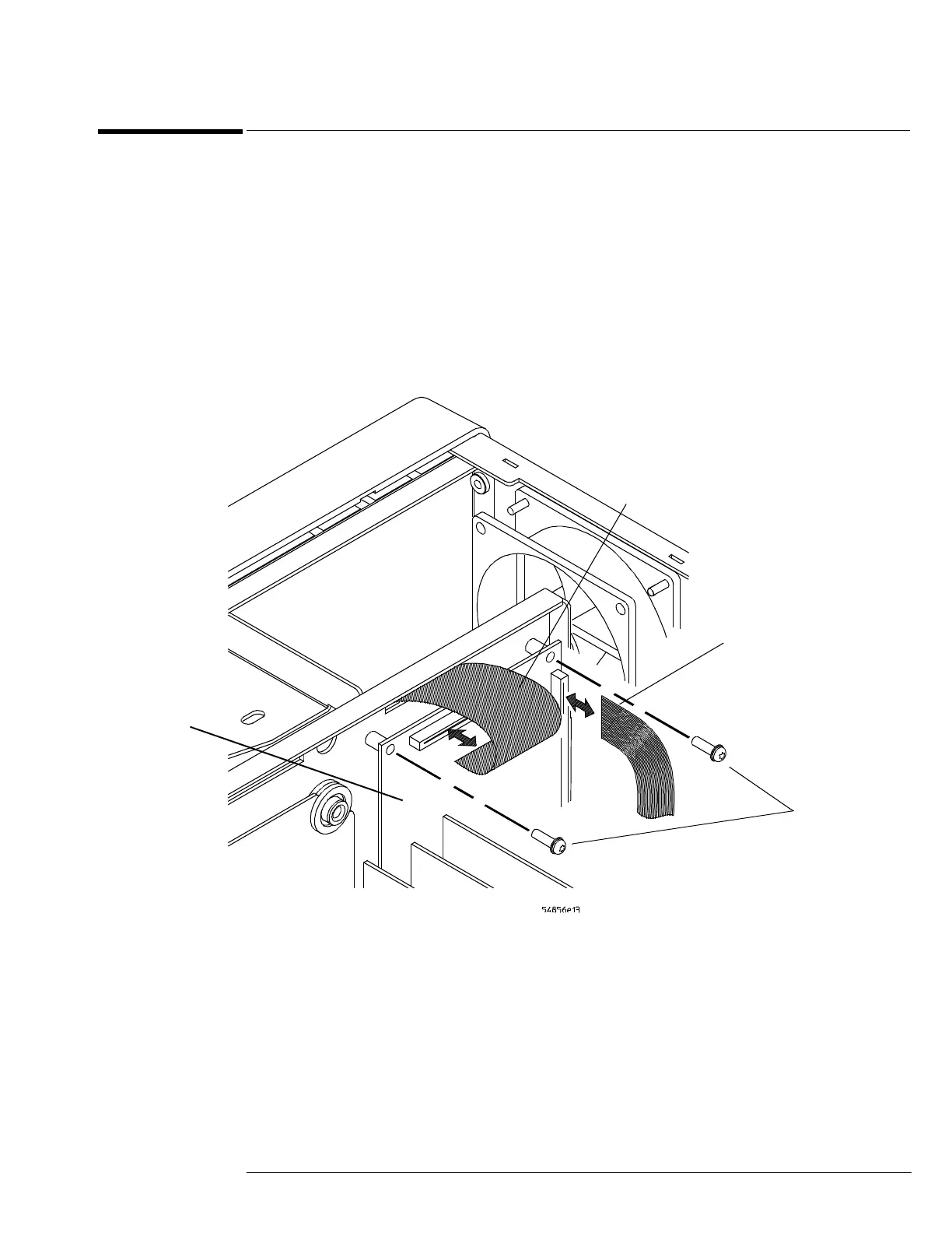
Figure 6-7
Remove the probe power and control assembly
4 Remove the two Torx T10 screws securing the probe power and control assembly to
the chassis.
5 Lift the probe power and control assembly out and away from the chassis.
Probe power
cable
AutoProbe
interface
cable
Torx
T10
Probe power
and control
board

 Loading...


