Chapter 6: Replacing Assemblies
To remove and replace the front panel assembly
113
4
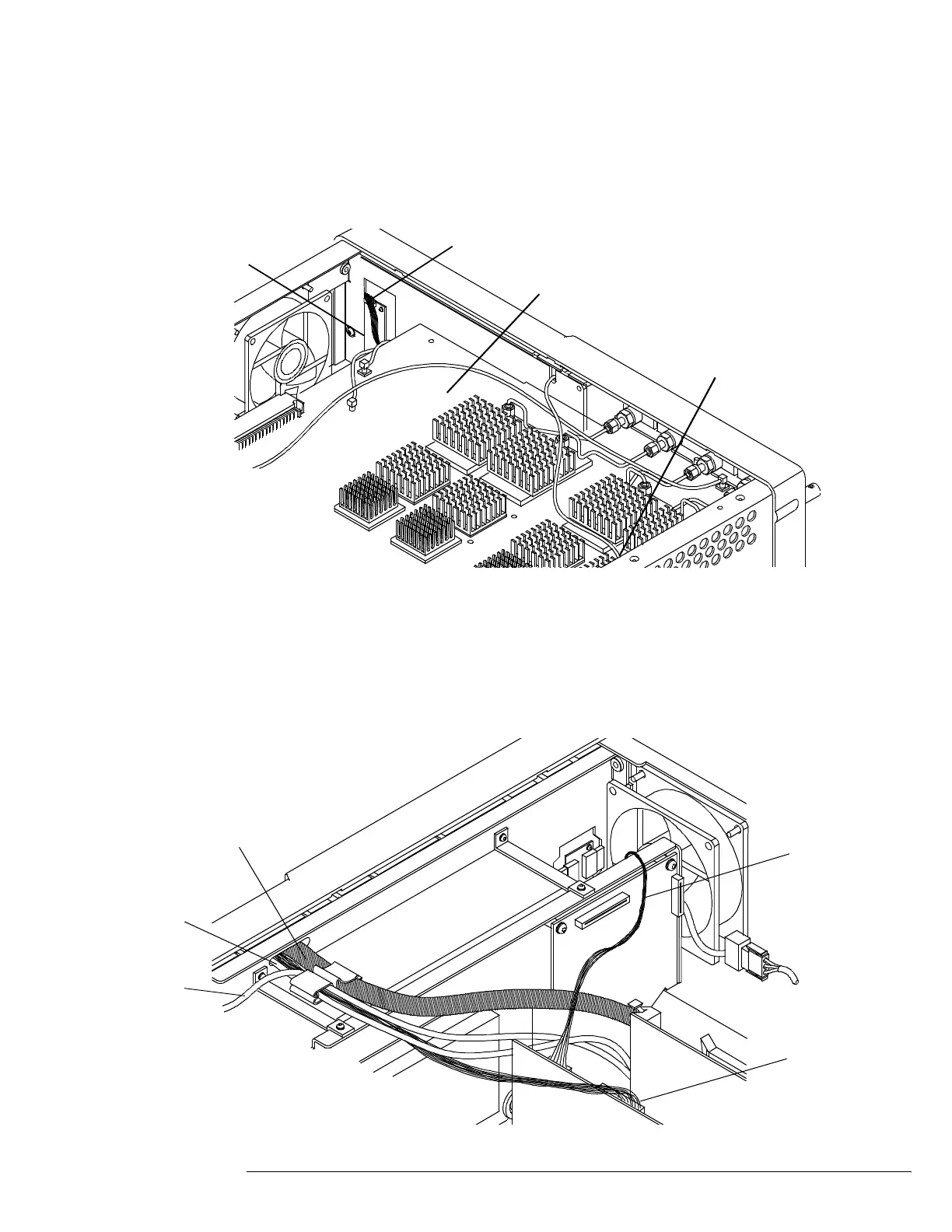
Disconnect the probe comp wire from the acquisition board.
If necessary, use pliers to remove the probe comp wire.
5
Disconnect the backlight inverter cable from the inverter board.
Figure 6-11
Removing probe comp wire and backlight inverter cable
6 Disconnect the flat-panel display driver cable and keyboard ribbon cable.
7 Use a sharp instrument to remove the silicone holding the pin headers of the touch
screen and front panel USB cables to their connectors on the motherboard. See Figure
6-14.
8 Disconnect the 2 USB cables from the motherboard.
Figure 6-12
Disconnecting the display driver cable, keyboard cable, touch screen USB and front panel USB cables
Acquisition board
Probe comp wire
Backlight inverter cable
Inverter board
Keyboard
ribbon cable
Backlight
inverter
cable
Flat panel
display driver
multi-colored
cable
Touch screen
USB cable
Front panel
USB cable

 Loading...


