Agilent N5161A/62A/81A/82A/83A MXG Signal Generators Service Guide
Troubleshooting
Checking ALC Operation < 3.2 GHz (N5183A)
1-49
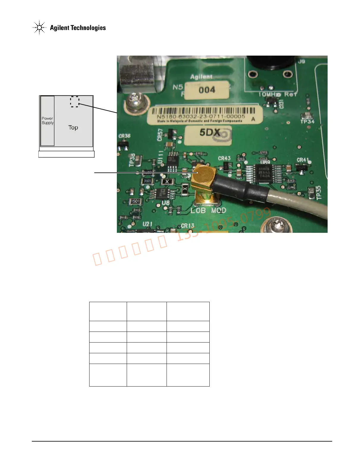
Figure 1-19 ALC LOB MOD Connector and Cable
5. Record the voltage in Table 1-7.
6. Measure the J15 connector center pin voltage at the remaining signal generator amplitude settings shown in Table 1-7.
7. Record the voltages in Table 1-7.
8. Turn off the RF (press
RF On/Off to Off).
9. Measure the J15 connector center pin voltage.
10. Record the measured voltage in Table 1-7.
11. Compare the measured voltages to the voltages listed in the Example Voltages column in Table 1-7.
• If the measured voltages do not decrease by approximately 1V for each 10 dBm reduction in power level, as shown in the Example
Voltages column in the table, or if there is no change in the voltage when changing power levels:
a. Replace the A7 Micro Deck.
Table 1-7 Measured Voltage Comparison
Power Level Example
Voltages
Measured
Voltage
+10 dBm +2V
0 dBm +1V
–10 dBm –0.130V
–20 dBm –1.30V
RF Off Decreases output
voltage more
than 8V
W14 modulator drive cable