3-38 Service Guide N5230-90014
Tests and Adjustments PNA Series Microwave Network Analyzers
Adjustments N5230A
Receiver Calibration Adjustment
The receiver calibration is used to adjust the network analyzer receivers for a flat response
across its full frequency range:
1. A power meter/sensor is connected to Port 1, as shown in Figure 3-15, to establish a
reference for flatness.
2. A cable is inserted between the power sensor and the test port, as shown in Figure 3-16,
to establish a reference for the cable.
3. The same cable is connected between test port 1 and test port 2, as shown in Figure
3-17, and a signal from Port 1 is used to adjust the “B” receiver at Port 2.
The adjustment is repeated using a signal from Port 2 to adjust the “A” receiver at
Port 1.
Data obtained during this adjustment are stored in the mxcalfile_pxx files on the hard disk
drive. The data are used in subsequent measurements.
If the hard disk drive is replaced, these mxcalfile_pxx files will be lost. Therefore, they
should be backed up (saved on a floppy disk) so that they can be restored. If using multiple
disk drives (e.g. classified and general usage), then these files must be replaced on each
individual disk drive.
These files can be recreated by performing another receiver calibration adjustment.
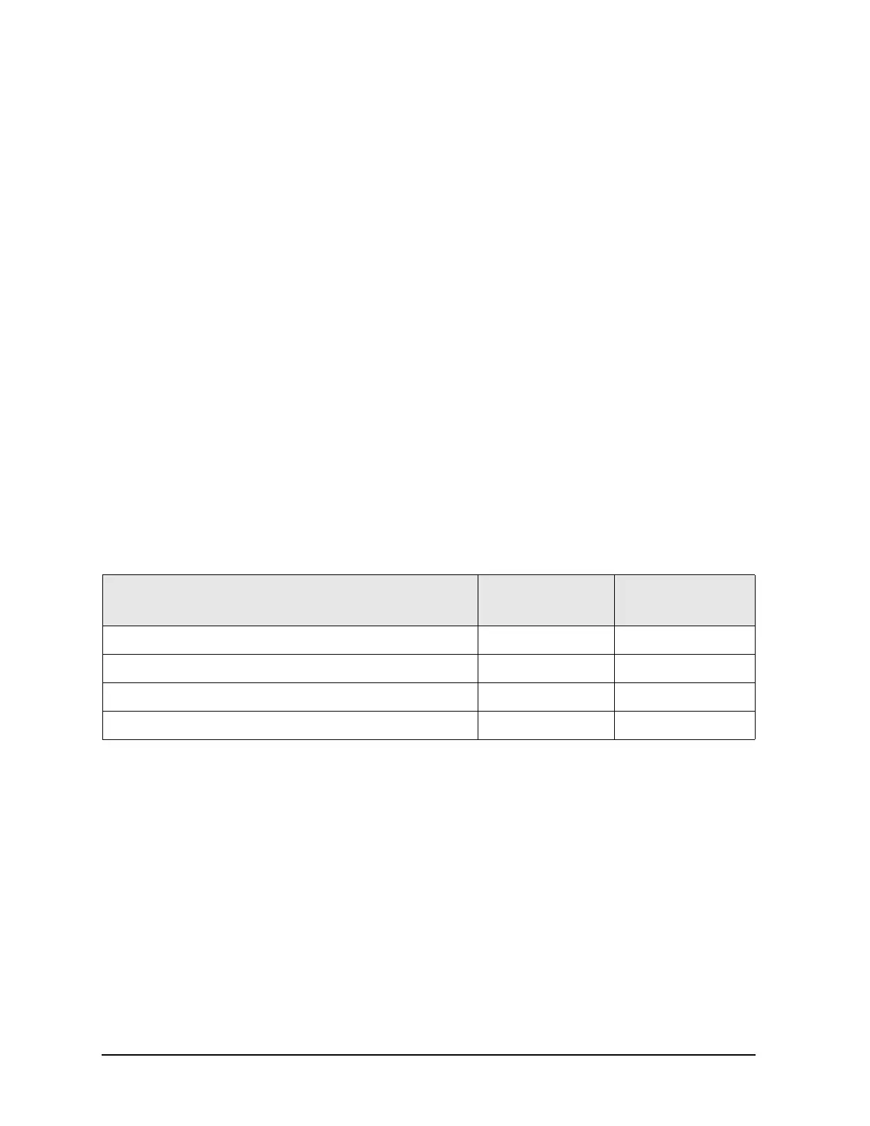
Equipment Used for the Receiver Calibration Adjustment
Procedure
1. Connect the equipment as shown in Figure 3-15. Connect a GPIB cable between the
network analyzer and the power meter.
Equipment Type
Model or
Part Number
Alternate Model
Part Number
Power meter E4418B/E4419B E4418A/E4419A
Power sensor, 3.5 mm E4413A 8485A
Adapter, 3.5 mm (f) to 3.5 mm (f) 83059B 85052-60012
RF Cable, 3.5 mm (f) to 3.5 mm (f) 85131C 85131E