22 Chapter 1
Getting Started
Setting Up Your Signal Analyzer and Signal Source
Getting Started
• You may also need accessories such as an open, short, directional
coupler, or directional bridge, depending on your particular
measurement.
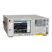
Connecting Your PSA Analyzer to a PSG-C, PSG-D, or
ESG-C Signal Source
Once you have the required equipment and cables, you are ready to set
up your measurement. You will need to connect the PSA analyzer and
the PSG-C, PSG-D, or ESG-C signal source, before configuring the
analyzer to recognize the source.
Connecting the Cables
1. Connect the signal source
TRIGGER OUT to the PSA spectrum
analyzer
TRIGGER IN. The analyzer TRIGGER IN connector must be
terminated in 50
Ω. This can be done by:
a. connecting a 50
Ω feedthrough directly to the PSA TRIGGER IN
connector and then connecting the BNC cable between the other
end of the feedthrough and the PSG or ESG-C
TRIGGER OUT
connector.
or
b. connecting a tee to the PSA
TRIGGER IN connector. Then
connecting one output of the tee to a 50
Ω. load and using the
BNC cable to connect the other tee output to the PSG or ESG-C
TRIGGER OUT connector.
2. Using the second BNC cable, connect
SWEEP OUT on the rear of the
signal source to
EXT TRIGGER INPUT on the front panel of the PSA
Series analyzer.
3. Using the third BNC cable, connect the PSG rear panel
10 MHz OUT
to the PSA rear panel
EXT REF IN.
4. Either connect each instrument to the LAN using two separate LAN
cables, or connect the two instruments together using a single LAN
crossover cable.
Configuring the PSA Series Analyzer
After the instruments are connected, you need to configure the PSA to
find the IP Address of the ESG-C or PSG Series signal source, so the
two instruments can communicate with each other.
Find the IP Address of the ESG-C or PSG Series signal source.
1. Press the
Utility key on the front panel.
2. Press
GPIB/RS-232 LAN, then LAN Setup to display the IP Address on
the second softkey label.
Enter the IP Address of the signal source into the PSA Series analyzer.

 Loading...


