MND172201 P a g e | 10 Software Revision 1.4.1
4. Installation
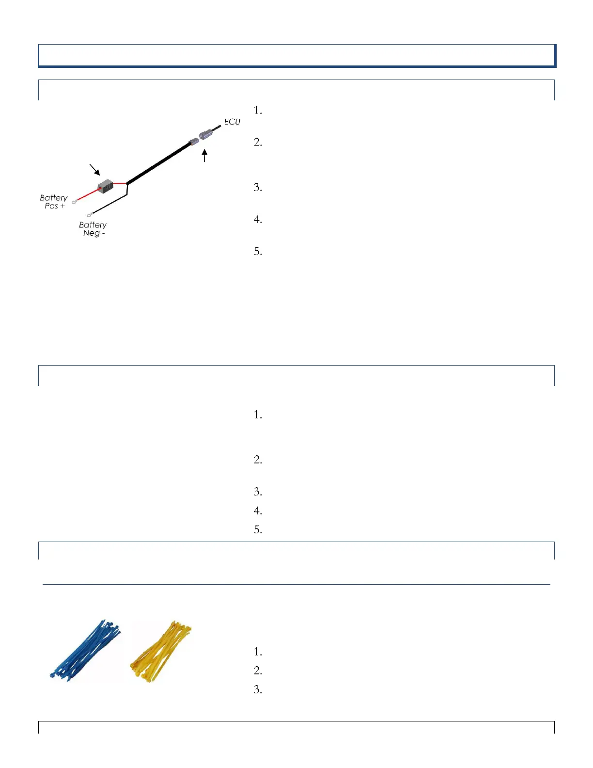
ECU Tractor Battery Harness
Select a mounting location for the battery harness so that the
DTP connector is at the tractor hitch
Connect the battery Harness to the DTP connector on the
ECU. (this connection should be at the tractor hitch to allow
for hitch disconnect)
Mount the ECU on the toolbar (main extension cables may
be needed) within 10ft of the tractor hitch
Connect red (+) power cable wire directly to the battery
positive terminal (30 amp fuse is required)
Connect the black (-) power cable wire directly to the
negative battery terminal
Do not connect the black cable to the tractor cab. Not
all tractor cabs are properly grounded.
When the ECU is not in use disconnect it from power. It may
drain the battery if not in use for long periods of time.
Antenna with Base Installation (Tow between Tank)
If using a Tow Between Tank, a magnetic base can be used to
place the antenna on top or front of a tank to achieve line of
site. (See the parts list associated with Figure 4-11)
Disconnect the antenna from the LEGEND S.A. Wi-Fi
ECU.
Connect the antenna to the magnetic base.
Connect the magnetic base cable to the ECU.
Mount the magnetic base and ECU in the desired location.
Colored Cable Tie Installation
Colored Cable Ties
The colored cable ties included in this kit are provided to assist in
easy installation and to differentiate between the two loops of
sensors
Use blue ties to attach Loop 1 cables.
Use yellow ties to attach Loop 2 cables.
Be sure to secure all cables, but DO NOT pinch cables too
tightly!
Tip:
Main Extension Cables may be needed to mount
the ECU in the desired location (Part#
9ARTM10, 9ARTM20).
Tip:
On 24 volt systems be sure to connect the
monitor to the correct battery. It must be
the one with its negative terminal connected
to the tractor chassis (ground). Connect the
red (+) lead of the monitor to the positive
(+) terminal of that battery and the black (-)
lead of the monitor to the battery.
Incorrect wiring could result in damage to
your monitor.