MND172201 P a g e | 20 Software Revision 1.4.1
Optional Sensor Installation
**Refer to Appendix B: Optional Sensors for more information**
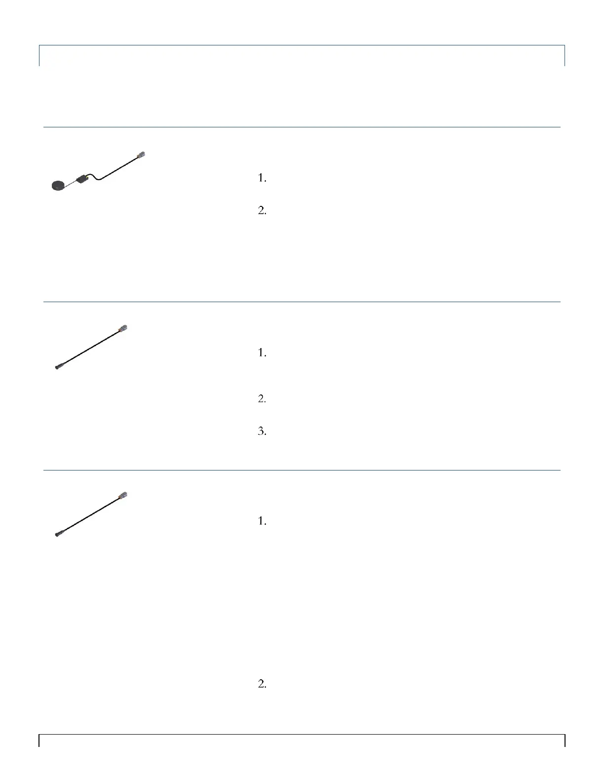
GPS/Radar Speed Sensor
Connect to the output of your GPS/Radar unit to connector
labeled Speed on Air Cart harness.
Turn to the Calibration and Operation portion of this manual
for information on how to set up optional sensors in the
system.
Wheel Speed Sensor
Install the Speed Sensor (Low RPM Reed Switch) and
magnet on a wheel or shaft that turns when the seeder is in
motion. Mounting within ½” of the magnet.
Connect the Speed Sensor to connector labeled Speed on the
Air Cart harness.
Turn to the Calibration and Operation portion of this manual
for information on how to set up optional sensors in the
system.
Automatic Work Switch
Install the Work Switch Sensor (Low RPM Reed Switch) and
magnet on the toolbar, mounting within ½” of the magnet.
The switch can be located such that the magnet closes the
switch when the drill is up, or closes it when the drill is down.
However, the Work Switch logic must be configured
appropriately. See Work Switch Setup.
Connect the Work Switch sensor to connector labeled Work
Switch on Air Cart harness.
Or
Splice into an existing Work Switch
Turn to the Calibration and Operation portion of this manual
for information on how to set up optional sensors in the
system.
Tips:
The monitor requires an open/close
circuit switch for a Work Switch. DO
NOT use a
powered switch without a
relay.
See Appendix Deutsch DTM
Connector Pin-out for more
information when connecting to an
existing Work Switch.
Tips:
The Single and Dual Loop ECU’s
require a pulse or radar style signal
output from the GPS.
A mating cable may be required from
the maker of the GPS/Radar unit.
A mating cable may be required from
the maker of the Speed Sensor.