MND172201 P a g e | 14 Software Revision 1.4.1
Y-Cable
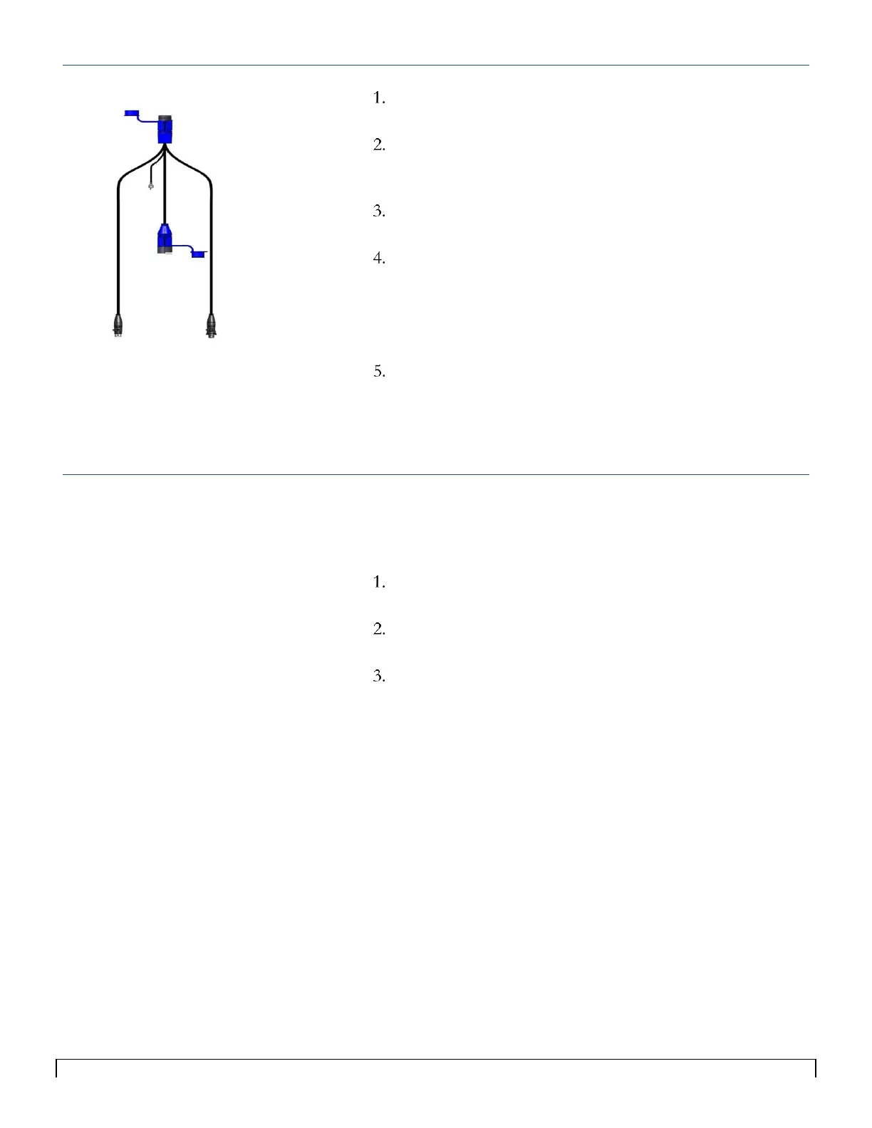
Select a mounting location for the Y-Cable in the center of
the implement.
Connect the large blue male end to the main cable (shown in
Figure 4-8), which is connected to the ECU on Loop 1 or
Loop 2.
Secure the ring terminal of the Y-Cable to the chassis of the
implement to ground the cable.
Route the Y-cable’s male sensor loop cable towards the far
left side of the implement using Sensor Loop Cables as
needed.
This end of the Y-cable will connect to sensor 1 on the first
manifold on the left side of the toolbar
Route the Y-cable’s female Sensor Loop Cable towards the
far right side of the toolbar, using Sensor Loop Cables as
needed.
This end of the Y-cable will connect to the last sensor in the
loop, on the last manifold on the right side of the toolbar
2
nd
Y-Cable on a Loop
On systems with more than 60 Seed Sensors, an additional Y-Cable
must be installed in the middle of the loop to improve power
distribution.
To prevent cable damage, route the cables so they follow the
hydraulic hoses whenever possible.
Connect the blue male end of the second Y-Cable to the blue
female end of the first Y-Cable.
Connect the second Y-Cable’s male and female Sensor Loop
Cables into the middle of the seed sensor loop (in place of a
Legened Loop cable).
Tip:
To prevent cable damage, rout the cables so
they follow the hydraulic hoses whenever
possible.