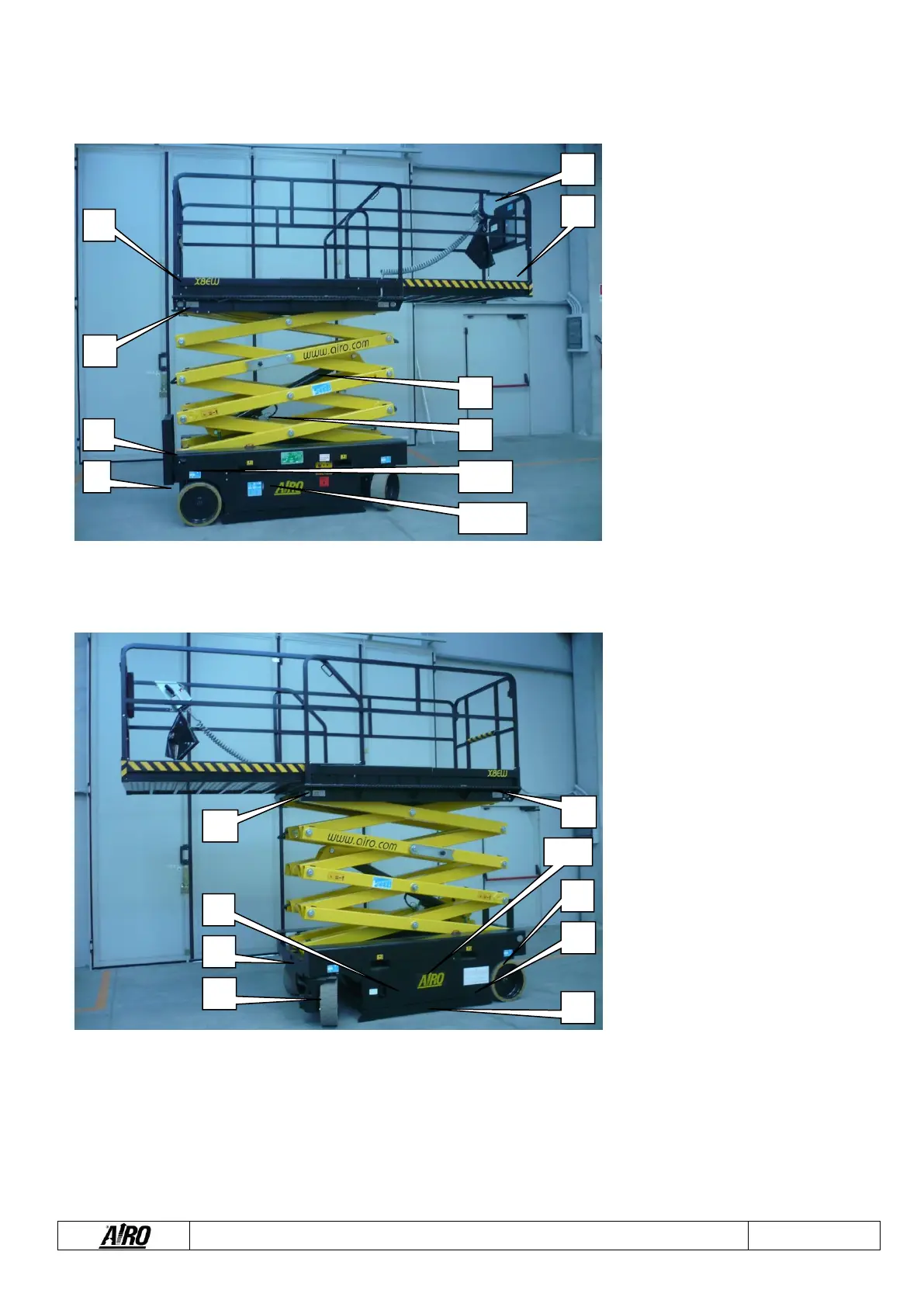
A. Platform control panel
B. Spirit level (optional) for visual check
of platform levelling
C. Lifting cylinder
D. Lowering control valve
E. Ground control panel
F. Electric control unit and inclinometer
G. Tank
H. Electric pump
I. Manual device for emergency lowering
J. Platform height control M1 microswitch
K. Electronic board of platform overload
controller
L. 230V socket (optional)
M. Overload controller sensors
N. Batteries
O. Battery charger
P. Parking brakes
Q. MPT1 and MPT2 microswitches to
control the position of the pot-hole
guards
R. Hydraulic drive motors
S. Steering cylinder
T. Bipolar power connector
U. Pot-hole guards