Use and Maintenance Manual – Series X – XS E RESTYLING
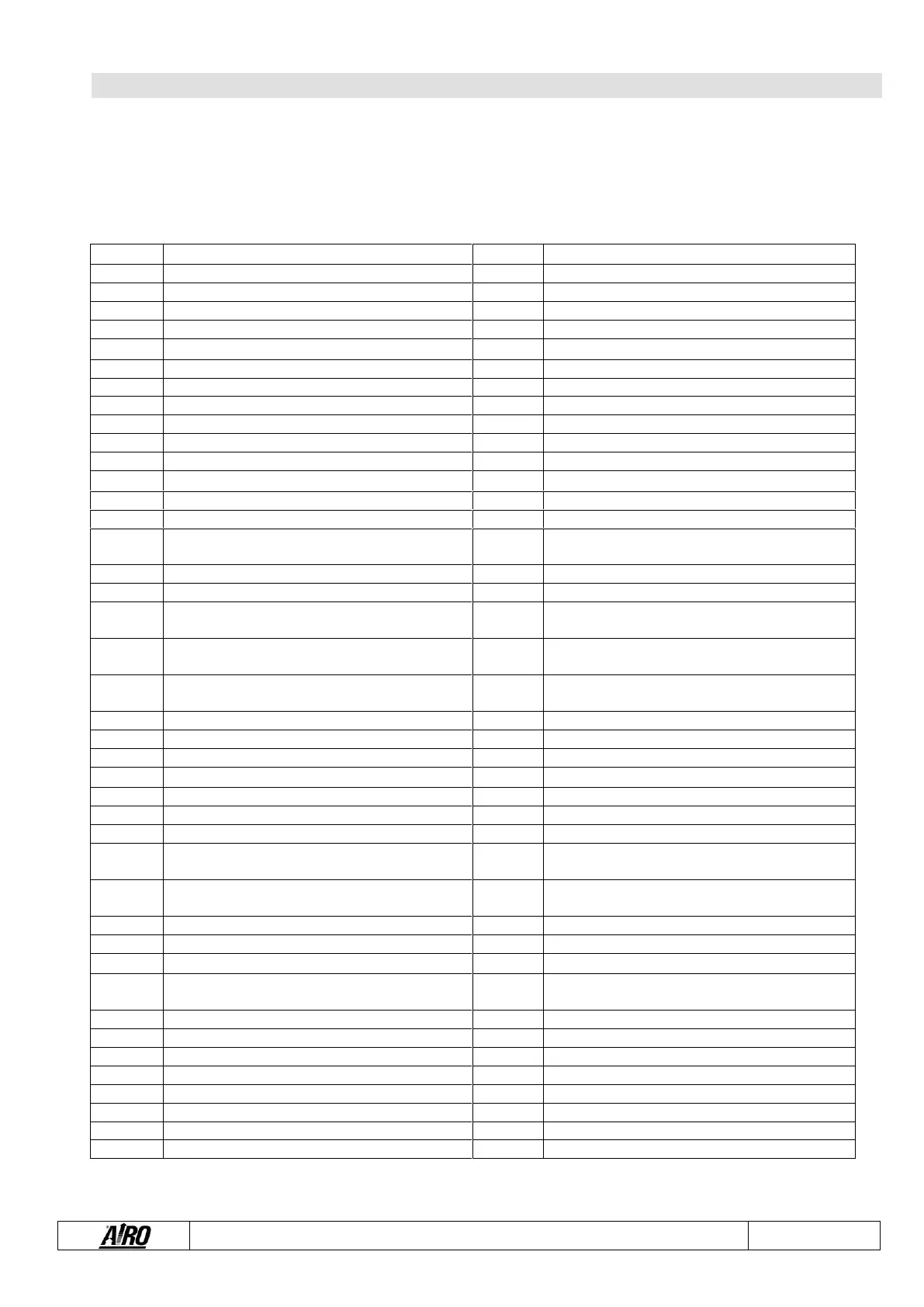
12. ELECTRIC DIAGRAM
WIRING DIAGRAM - STANDARD MACHINES
045.08.011 – 045.08.012
X8EW-WIND – X8EN – X10EW – X10EW-WIND – X10EN – X12EW – X12EW-WIND – X12EN – X14EW – X14 EN
X16 EW - XS7 E RESTYLING – XS8 E RESTYLING LIGHT – XS8 E RESTYLING – XS8 E RESTYLING WIND - XS9 E
RESTYLING
EV4 solenoid valve control – Lifting
Green led platform controls enable
EV11 solenoid valve control – By pass
Red led platform general alarm
Red led platform overload alarm
AV2 platform audible alarm
5V - Positive joystick potentiometer
-batt- Negative joystick potentiometer
Platform controls cable – sheath 1
Joystick potentiometer signal
Platform controls cable – sheath 2
Positive limit switch power + system led ON
Forward drive solenoid valve
Backward drive solenoid valve
Red led platform flat battery alarm
Positive platform controls
Left steering solenoid valve
Positive platform controls
Right steering solenoid valve
Fast drive solenoid valve
Backward / Lowering control
Forward / Lifting control
M1 limit switch (contact closed with platform
lowered)
Platform Lifting / Lowering selection
MPT limit switch (contact closed with pot-hole guard
lowered)
MPT limit switch (contact closed with pot-hole guard
lowered)
Platform emergency switch
M1 limit switch signal (contact closed with platform
lowered)
Jumper between EV5 and EV8 sheaths
MPT limit switch signal (contact closed with pot-
hole guards lowered)
Jumper between MPT1 and MPT2 sheaths
+24V – Positive battery from battery charger relay
Positive from ground emergency button
line remote switch TLR control and hour-meter
signal
Positive from platform emergency button
EV2 solenoid valve control – Forward drive
EV3 solenoid valve control – Backward drive
EV8 solenoid valve control – Left steering
EV5 solenoid valve positive control - Lowering
EV9 solenoid valve control – Right steering
EV10A / EV10B solenoid valve control – Fast drive