12
GENERAL REQUIREMENTS
Strictly follow the directions outlined in this manual:
• This system must be installed by a qualified technician.
• Make all the connections with total absence of power.
• Set and connect the elements in accordance with the electronic regulations in force.
• In order to connect the elements of the system, use the cable: shielded twisted cable formed by 4 wires
(AWG 20 4 wired).
• Do not connect the "-" pole in the "+" terminal. It may damage the device.
• For elements externally powered at 110/230 Vac, for the communications, it is only necessary to connect the poles "A"
and "B" of the bus. Connecting the "+" and " -" power poles is not recommended.
• To connect the actuators to the actuator outputs, use a 2-core section cable (0.75 mm
2
).
• Follow the color code for all the elements of the system.
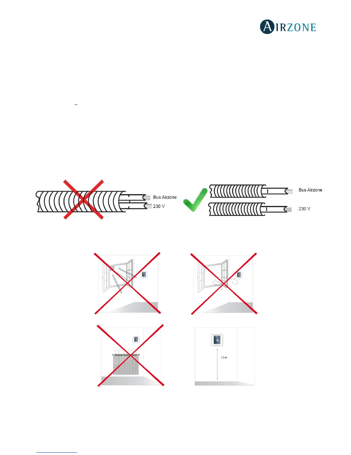
• Do not place the system bus close to lines of force, fluorescent lights, motors, etc. It might cause interference on the
communications.
• It is recommended to label all the actuator outputs in order to facilitate their subsequent identification.
• Follow these recommendations to locate the thermostats:
Important: According to the current local and national regulations, it is mandatory to add a switch (or other element to
disconnect the system) to the external supply wiring so that a constant separation between poles is guaranteed. The system
will restart automatically if the supply is eventually turned off.
 Loading...