58
COMMUNICATION GATEWAYS (AZVAFGTXXX)
The communication gateways incorporate LEDs that detect unusual operations.
Check the distribution of the LEDs in the data sheet supplied along with the product.
Power LED D1: Off
• Check the air conditioning unit is powered.
• Check the connections between the gateway and the AC unit and between the gateway and the thermostat of the AC
unit (if applicable).
• Verify the status of the connectors in the wiring connecting gateway-AC unit and/or gateway-AC thermostat.
• Verify the gateway is properly connected to the AC unit port of the control board.
Microprocessor operation LED D2: Not blinking
• Contact the Airzone after-sales department, the microcontroller does not operate properly.
Communication LEDs D3 and D4: Not blinking
• Verify the gateway is properly connected to the AC unit port of the control board.
LEDs D5 and D6 of communication with the indoor unit: Not blinking
• Check gateway-AC unit connection.
LEDs D7 and D8 of communication with the indoor unit: Not blinking
• Check the Gateway-AC unit thermostat connection.
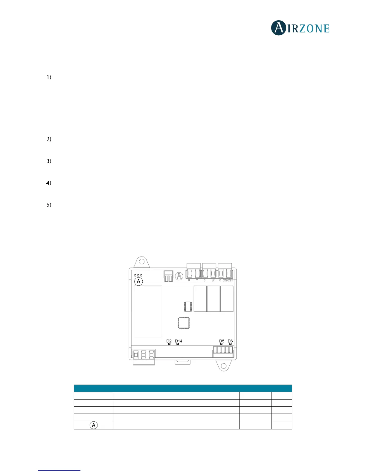
0-10 V FANCOIL CONTROL GATEWAY (AZVAFGTF10)
Airzone 0-10 V Fancoil control gateways incorporate LEDs that detect malfunctions.
Fig. 78
 Loading...