EasyManuals Logo

Airzone AZVAFR Series User Manual

Airzone AZVAFR Series
63 pages
To Next Page IconTo Next Page
To Previous Page IconTo Previous Page
Page #28 background imageLoading...
Page #28 background image
28
5-RELAY FANCOIL CONTROL GATEWAY (AZVAFGTF5R)
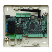
Fig. 44
Assembly
The 5-Relay Fancoil control gateway is mounted on DIN rail (Fig. 45) or on wall (Fig. 46). This module is externally powered at
110/230 Vac. It is should be placed and mounted in accordance with the current electrotechnical regulations.
Fig. 45 Fig. 46
Note: To remove the module on DIN rail, pull the tab down to release it.
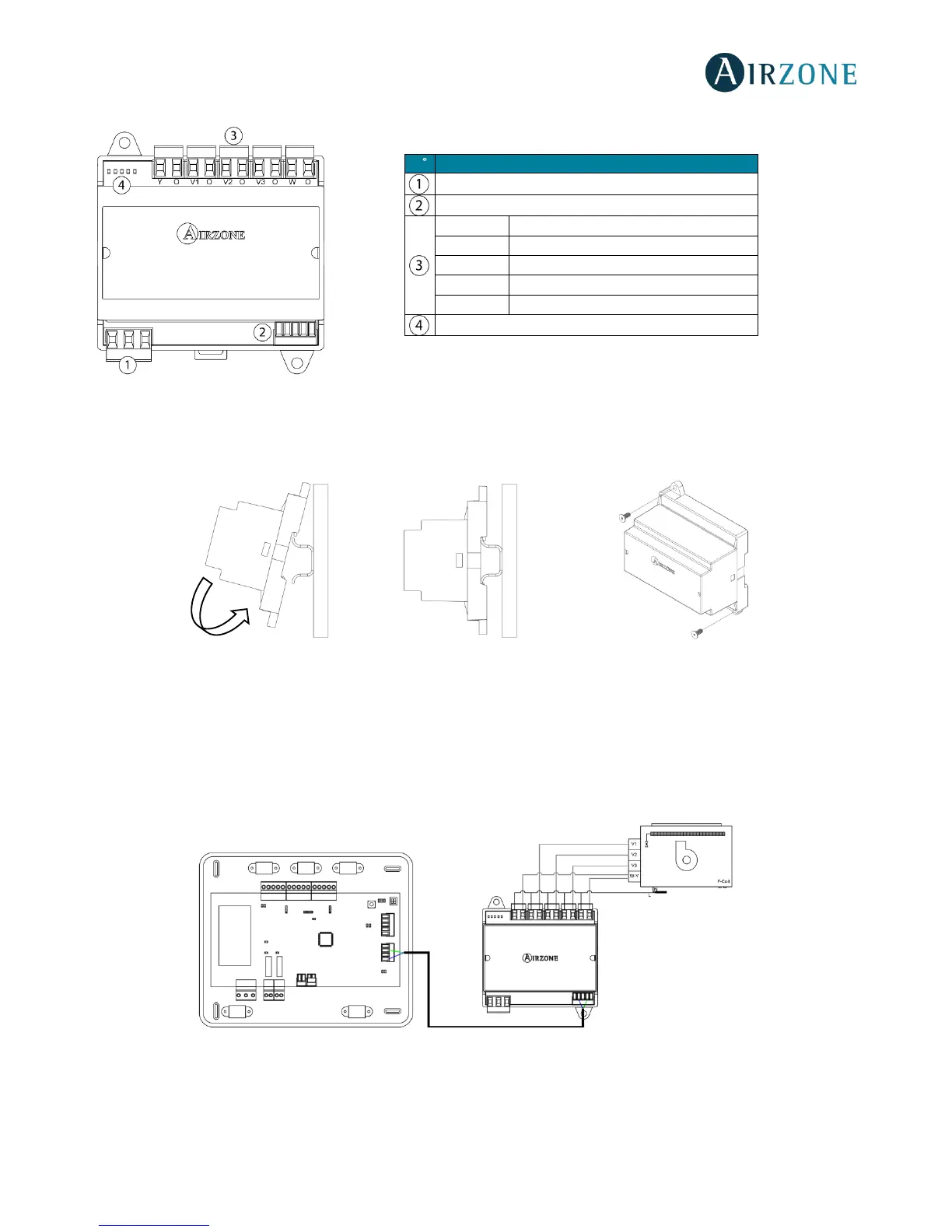
Connection
The 5-Relay Fancoil control gateway is connected to the AC unit bus of the main board (Fig. 47 and 48).
Wiring diagram, 2-pipe installation
Fig.47
N
Description
Power supply
AC unit bus
Y-O
Cooling air demand
V1-O
Speed 1
V2-O
Speed 2
V3-O
Speed 3
W-O
Heating air demand
Status LEDs

Table of Contents

Questions and Answers:

Question and Answer IconNeed help?

Do you have a question about the Airzone AZVAFR Series and is the answer not in the manual?

Airzone AZVAFR Series Specifications

General IconGeneral
BrandAirzone
ModelAZVAFR Series
CategoryControl Unit
LanguageEnglish

Related product manuals