24
Connection
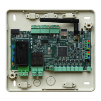
The Relay Radiant Heat Control Module is a device that is connected to the Airzone Connection Bus of the control board
(Fig. 28).
Control relay specs: 24/48 Vac (voltage-free). To control elements of a greater power, it is recommended the use of contactors
in accordance with the power required. Remember to connect the neutral connector directly from the circuit to the element to
be controlled.
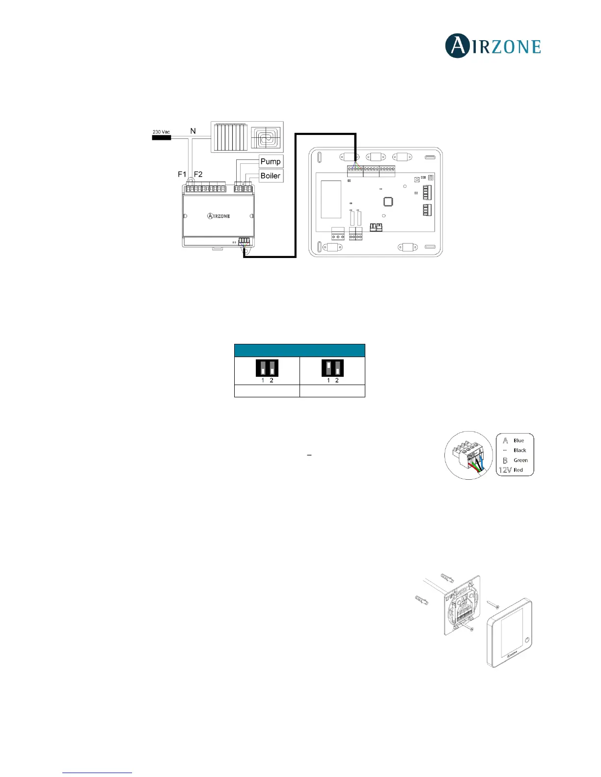
The SW2 microswitch configuration (zone ID) is as follows:
Example: The relay to control a radiant element of a module with address 6 is the R1 of the Relay Radiant Heat Control Module
with the address set for the zones 6-10.
It has a 4-pin terminal to connect it to the AC unit bus of the main board. Use the proper cable:
shielded twisted pair 4 wired: 2x0.22 mm
2 +
2x0.5mm
2
(AWG 20 4 wired). Attach the wires with
the terminal screws following the color code (Fig. 29).
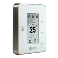
WIRED THERMOSTATS (AZVAFBLUEFACEC / AZVAFTHINKC / AZVAFLITEC)
Assembly
Airzone thermostats are mounted on the wall through a support. It is recommended not to locate it more than 40 meters away
from the control board. To fix it to the wall, follow these steps (Fig. 30):
• Separate the back part of the thermostat from the wall support and make all the
connections.
• Fix the back part of the thermostat to the wall.
• Place the display on the support once it is fixed.
 Loading...