29
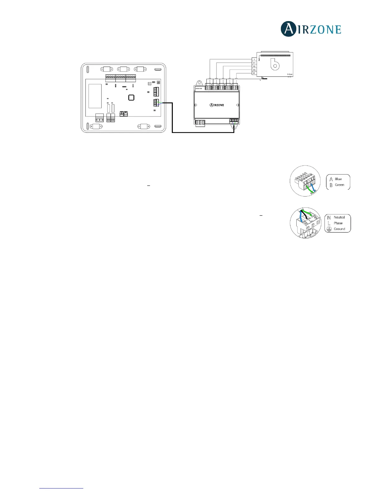
Wiring diagram, 4-pipe installation
Fig. 48
Control relay specs: I
max
= 10 A at 110/230 Vac, voltage-free. Note that to control elements with a greater power, it is
recommended to use contactors in accordance with the power required.
It has a 5-pin terminal to connect it to the AC unit bus of the main board. Use the proper cable: shielded
twisted pair 2 wired: 2x0.22 mm
2
(AWG 24 2 wired). Attach the wires with the terminal screws
following the color code (Fig. 49).
It is connected to the module through a 3-pin terminal. To do that, use a 3x1.5 mm² (AWG 15 3 wired)
cable. Attach the wires with the terminal screws following the color code (Fig. 50).
Important: According to the current local and national regulations, it is mandatory to add a switch (or
other element to disconnect the system) to the external supply wiring so that a constant separation between poles is
guaranteed. The system will restart automatically if the supply is eventually turned off.
 Loading...