17
Protection temperature probe connector
It measures the outdoor temperature through an external probe. We recommend the use of this probe when using
electromechanical units or NON-Inverter units (when it is necessary to control the return temperature of the units).
Auxiliary heat outputs
The system includes auxiliary heat, connect the auxiliary heat relays of the VAF Control board to the elements to control. Control
relay specs are I
max
: from 1 A to 24-48 V, voltage-free. To control elements of a greater power, it is recommended to use
contactors in accordance with the power required.
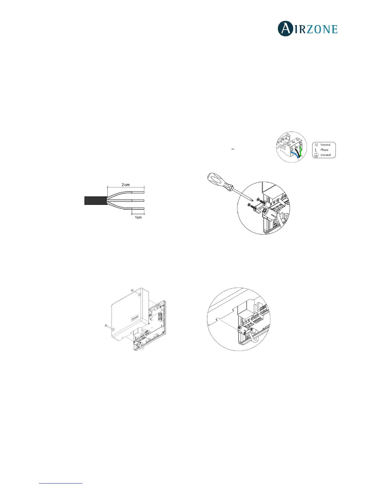
Power supply connector
This connector powers the control board and all the elements connected to it. Externally powered
at 110/230 Vac. It is connected through a 3-pin terminal. Use a 3x1,5 mm² (AWG 15 3 wired) cable.
Attach the wires with the terminal screws following the color code (Fig. 7). For added security,
secure the wires using the turret (Fig. 8).
Fig.8
Important: According to the current local and national regulations, it is mandatory to add a switch (or other element to
disconnect the system) to the external supply wiring so that a constant separation between poles is guaranteed. The system
will restart automatically if the supply is eventually turned off.
Remember: Once all the connections are made, make sure you replace the cover properly (Fig. 9).
Fig. 9
 Loading...