Wiring plan example 17 (38)
Installation Manual T-Rx 1000/1500 FSK12 FSK12 Version: B4 Document-ID: 945814-000 Author: SH
7.2.3 Antenna cabling
The maximum allowed length of the antenna cables is 10 meters.
The connectors on the receiver are of type SMA for radio band 400MHz and 800MHz. For radio
band 2,4 GHz RP-SMA is used.
Install the antenna cables separated from high voltage or high current cables/devices.
If the antenna is installed outdoors, there is a risk that dangerous voltages may
enter the antenna cable. To minimize this risk a DC block shall be used. DC
blocks are coaxial components that prevent the ow of low and direct current
(DC) frequencies while offering minimum interference to RF signals. Suitable
models have capacitors in series with both the inner and outer conductors.
Åkerströms can provide one suitable DC block 944498-000.
8 Wiring plan example
Denitions
R/M Remote/manual mode changeover switch
Stop Device Device that sets the controlled object in a safe state
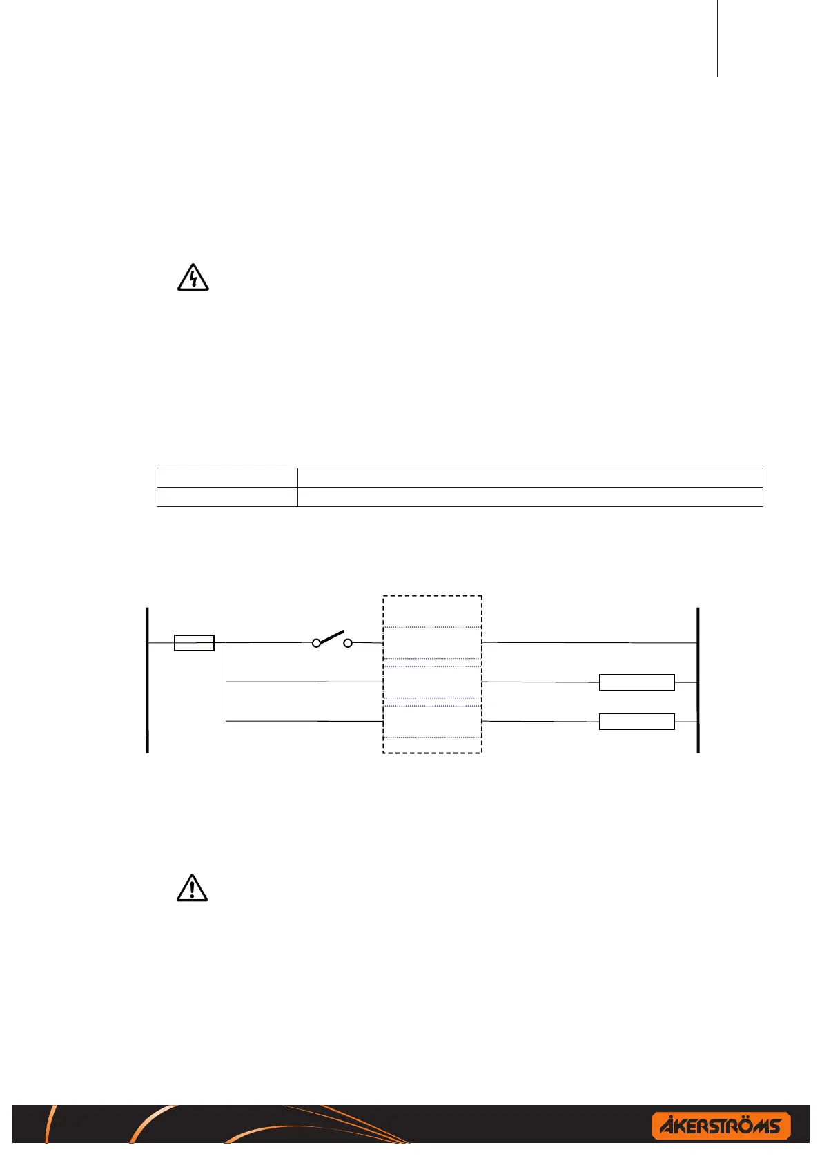
8.1 Receiver power and RCSS
RCSS
2
RECEIVER
LOGIC
1
RECEIVER
1 5
9 13
17 21
STOP DEVICE 1
STOP DEVICE 2
Figure 5. Wiring example for Receiver power and RCSS
!
Both RCSS1 and RCSS2 must be fed with power (pin 9 and 17)
RCSS1 and RCSS2 outputs may not be tied together
!
Always use a separate switch for switching the receiver ON/OFF
To reach full safety both RCSS1 and RCSS2 shall be used
 Loading...