SIL information 8 (38)
Installation Manual T-Rx 1000/1500 FSK12 FSK12 Version: B4 Document-ID: 945814-000 Author: SH
3.2 General Description
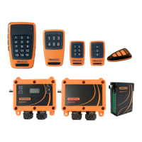
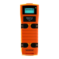
The transmitter is a hand held unit intended for being carried by the operator. The transmitter
provides a series of switches and joysticks allowing the operator to control automotive applica-
tions. The transmitter may also be equipped with some LEDs, a buzzer and/or a display in order
to provide to the operator optical and acoustics advices related to the state of the system.
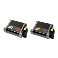
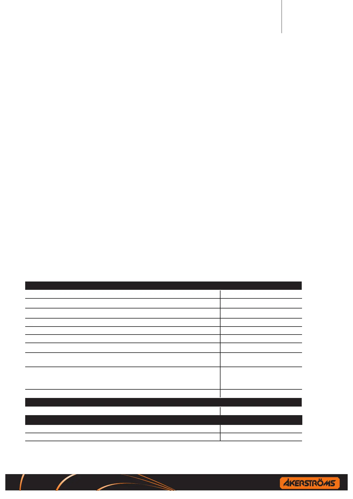
The receiver is a xed unit intended for being installed on the controlled object. It provides a
set of outputs that are driven accordingly to the commands performed by the operator on the
transmitter; that is accordingly to the way the operator sets the switches and the joysticks of the
transmitter. The outputs are also used for providing information about the working condition of
the T-Rx system. For instance, the “Safety outputs” are also used for notifying an emergency
condition: they provide the related information though it is not possible to know how the con-
trolled object manages this information.
The system has a dened “Safe State” of both the transmitter and of the receiver.
The “Safe State” of the transmitter is when no messages are transmitted or when transmitted
messages include active stop command.
The “Safe State” of the receiver is when the “Safety outputs” are inactivated.
The safety of the “T-Rx system” involves mainly the states of its outputs regardless the con-
trolled object assemblies that are driven by the outputs themselves, provided that it has to be
suitable for being used as a part of a radio remote control system.
The interface between the T-Rx system and the controlled automotive application is intended for
being implemented by means of a specic interface assembly; this assembly is not part of the
T-Rx system and for this reason is not considered in the T-Rx life cycle. Nevertheless, the T-Rx
system is intended to be safe without the use of any other external assembly or system.
3.3 Measures for probability of hardware failures
Receiver Stop function:
Probability of dangerous failure PFH = 9.6*10
-8
(hours
-1
)
Failure of the safety function without detection from internal or external diagnostics
λ
DU
= 107 FIT
Failure of the safety function with detection from internal or external diagnostics
λ
DD
= 1423 FIT
Proof test interval 10 years
Diagnostic test coverage DC = 93%
Diagnostic test interval Continuous testing
The failure rate of the diagnostics, due to random hardware failures.
λ
DIAG
= 659 FIT
Any additional information (for example repair times) that is necessary to allow the deriva-
tion of the mean repair time (MRT) following detection of a fault by the diagnostics
MRT = 8 hours
All information that is necessary to enable the derivation of the safe failure fraction (SFF)
of the elements as applied in the E/E/PE safety-related system, including the classication
as type A or type B.
Type B element
λ
S
= 1883 FIT
SFF = 96.9%
Level of hardware fault tolerance HFT = 1
Radio communication between transmitter and receiver:
Probability of dangerous failure 2.54-10
-10
(hours
-1
)
Stop function for a complete system:
Reaction time on STOP function Maximum 550ms
Safety parameters for STOP function ISO13849-1:2006 category 3 PL d
 Loading...