Wiring plan example 18 (38)
Installation Manual T-Rx 1000/1500 FSK12 FSK12 Version: B4 Document-ID: 945814-000 Author: SH
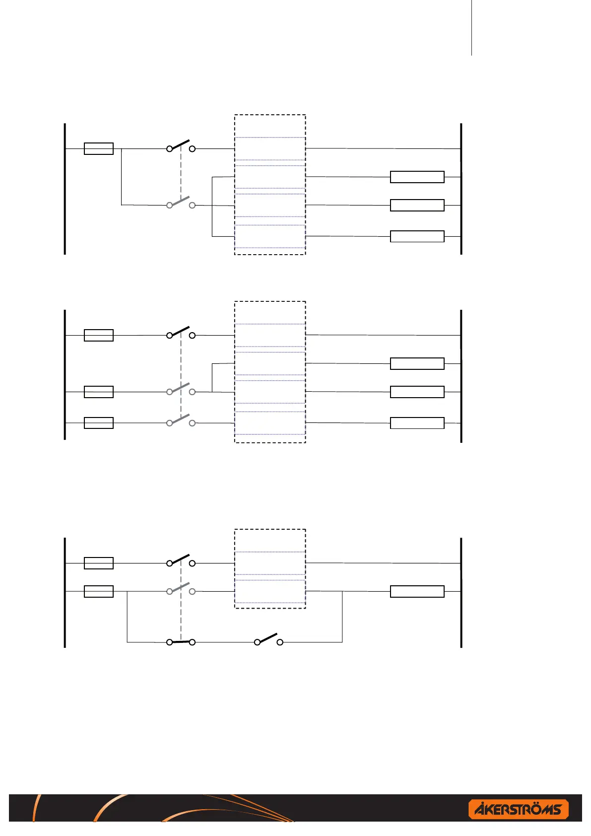
8.2 Single/multiple fuses
RCSS
RECEIVER
LOGIC
RCSS
1
RECEIVER
1 5
9 13
17 21
STOP DEVICE 1
STOP DEVICE 2
PWM
59 52
2
0
Figure 6. Wiring example for Single fuse
RCSS
RECEIVER
RCSS
RECEIVER
1 5
9 13
17 21
STOP DEVICE 1
STOP DEVICE 2
PWM
59 52
Solenoide
LOGIC
1
2
0
Figure 7. Wiring example for multiple fuses
8.3 Control devices in parallel with receiver
RECEIVER
1 5
PWM
59 52
Solenoide
LOGIC
0
Figure 8. Wiring example for Control devices in parallel with receiver
!
If an external push button or other device is connected in parallel with the receiver it
shall always have the same feeding point and if necessary also be connected to the R/M
switch.

 Loading...