Installation 14 (38)
Installation Manual T-Rx 1000/1500 FSK12 FSK12 Version: B4 Document-ID: 945814-000 Author: SH
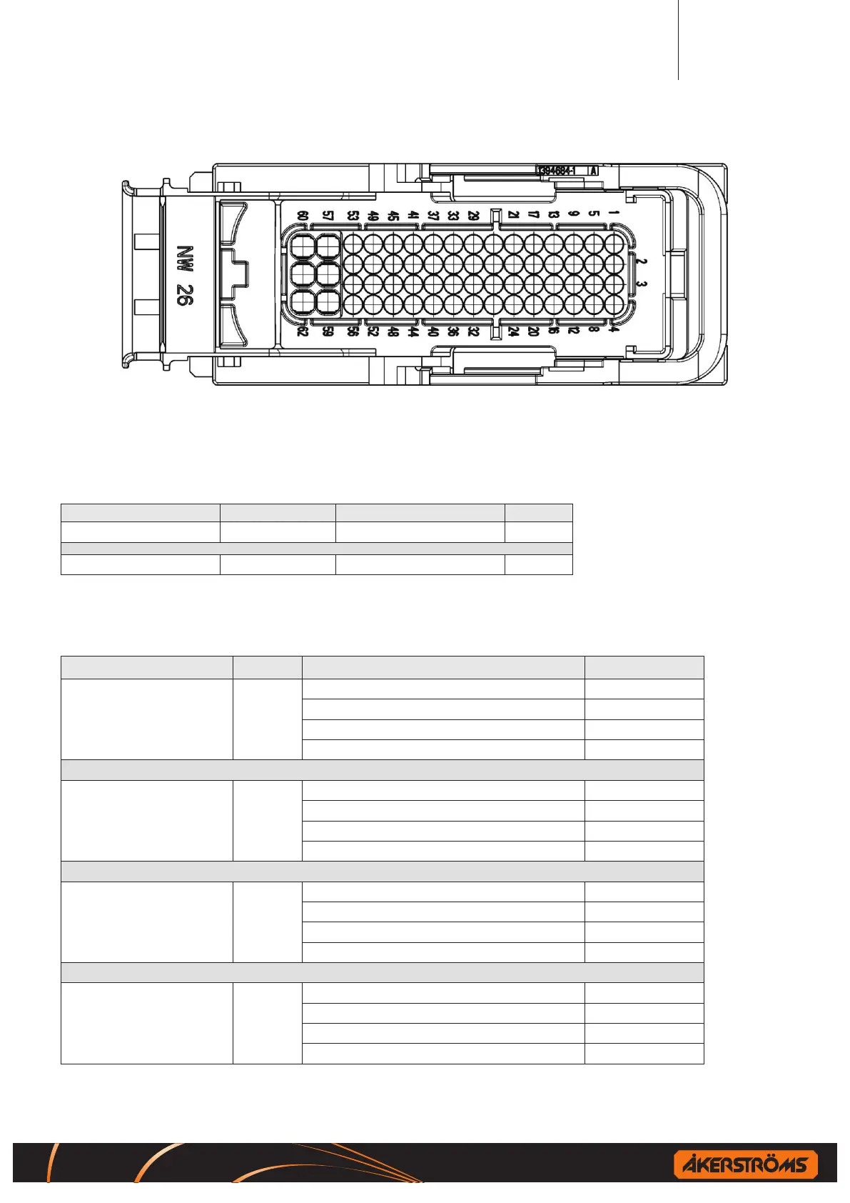
7.1.3.1 Interface connector pin layout
Figure 4. Interface connector, cable part
7.1.3.2 Connector pin assignment
7.1.3.2.1 RCSS outputs
Supply line Pin Function Pin
VDD_1 9 RCSS1 13
VDD_2 17 RCSS2 21
7.1.3.2.2 PWM outputs
Supply line Pin Function Pin
VDD_3 59
output PWM0 52
output PWM1 56
output PWM2 51
output PWM3 54
VDD_4 62
output PWM4 53
output PWM5 50
output PWM6 49
output PWM7 45
VDD_5 61
output PWM8 41
output PWM9 37
output PWM10 33
output PWM11 29
VDD_6 60
output PWM12 25
output PWM13 26
output PWM14 22
output PWM15 18

 Loading...