Interface connector assembly 31 (38)
Installation Manual T-Rx 1000/1500 FSK12 FSK12 Version: B4 Document-ID: 945814-000 Author: SH
15.3.1.2 Contact loading
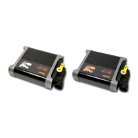
One has to pay attention to the correct orientation of contacts, which is shown in Figure 16.
With correct orientation the locking is signalized by a stop (contacts incl. crimps are located in
the cavi ties completely) and a metallic “click” noise.
Right orientation
Wrong orientation
Figure 16. Contact orientation
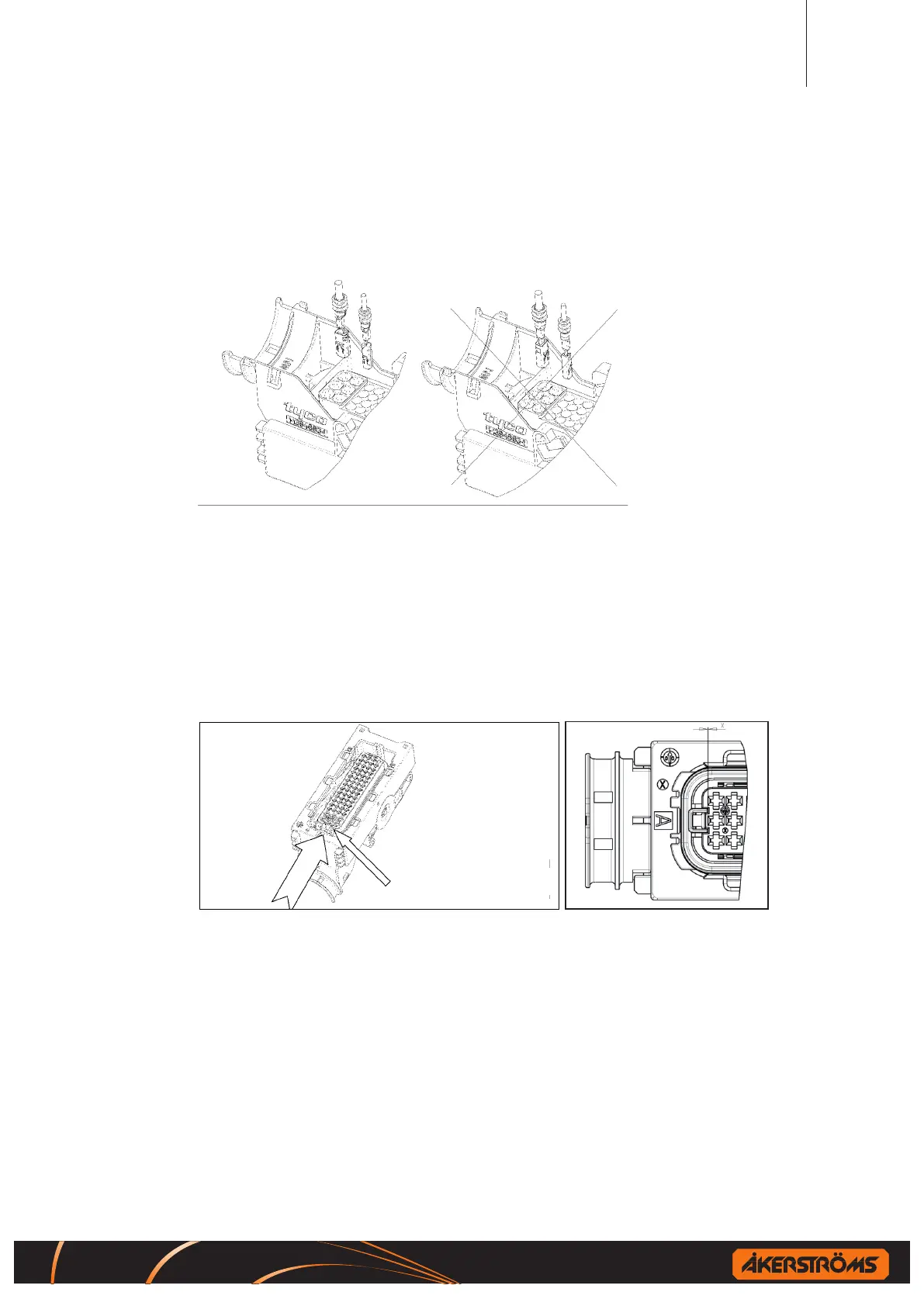
15.3.1.3 Final locking of secondary locking device
The housing described in this specication is equipped with a not- to- lose pre assembled
secon dary locking device. Delivery state is the pre locked position. In this position the AMP
MCP2.8™ SWS and AMP MCP1.5K™ SWS contacts (see chap. 15.2.2) can be loaded. After-
wards the secondary lock ing device has to be moved into the nal locking position with the help
of a simple aid or tool (for in stance a suitable screwdriver). Reaching the nal position is signal-
ized by a “click” noise.
Secondary locking (yellow)
Close
Figure 17. Secondary contact locking
15.3.1.4 Unlocking the secondary locking
To unlock the secondary locking device, reverse proceed with 15.3.1.3.
15.3.1.5 Extracting the contacts
To extract single contacts, the secondary locking must be moved into the unlocked position as
shown in Figure 18 at rst. See application specication of contacts for suf cient unlocking
respective extracting tools. The tool has to be inserted from connection side into the according
cavity of housing against the stop; the contact will be unlocked thereby. The tool remains in that
position and by pulling the cable the contact can be taken out.
 Loading...