Port Features
Page 96 7750 SR Interface Configuration Guide
Sample APS Application:
MC-APS for ATM SAP with ATM VPLS Service
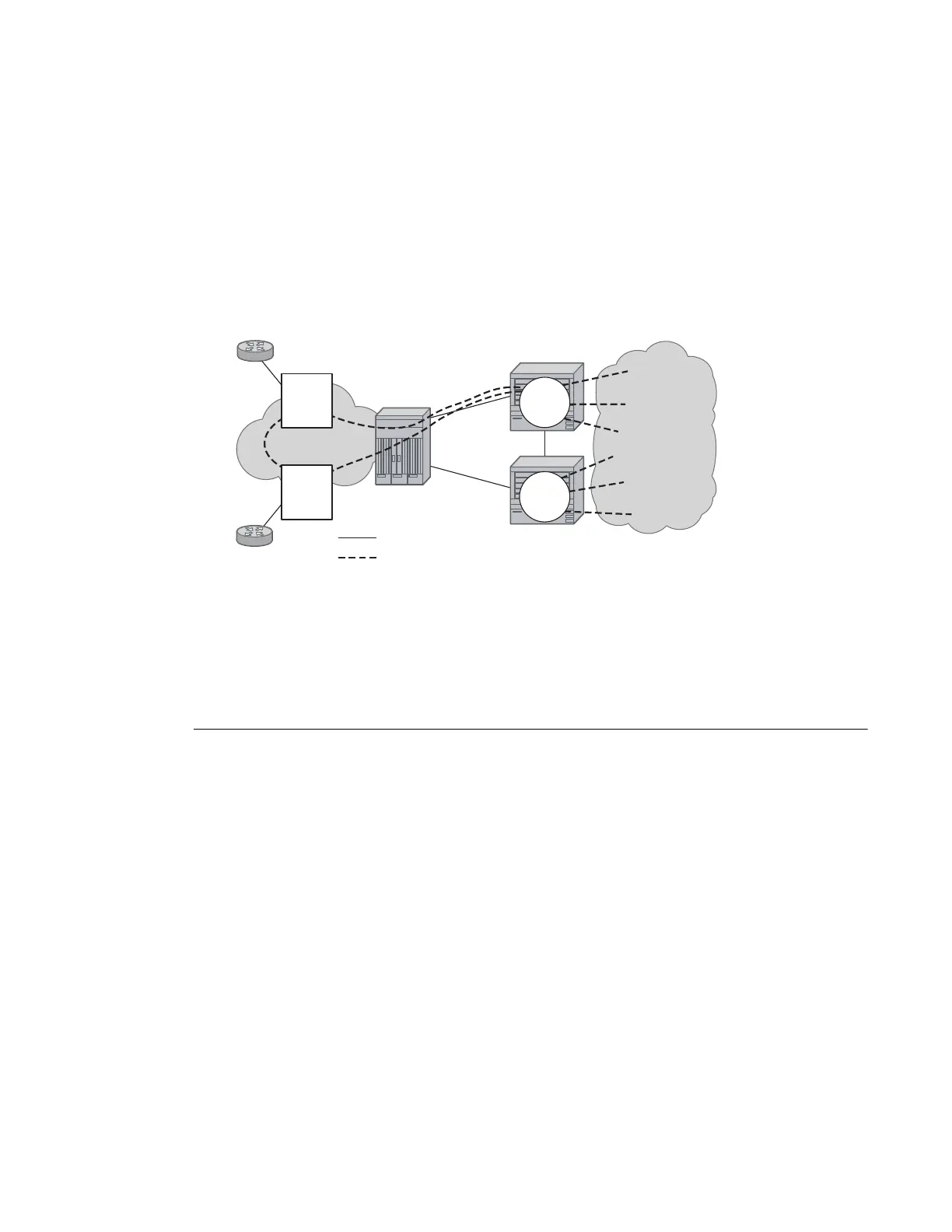
In Figure 17, service router A is connected to the ATM switch or 7670 through an OCx ATM 1
link. This link is configured as the working circuit. Service router B is connected to the same ATM
switch or 7670 through an OCx ATM 2 link. This link is configured as the protection circuit.
Figure 17: Multi-Chassis APS Application
Communication between service routers A and B is established through link 3. This link is for
signalling. To guarantee optimum fail-over time between service routers A and B, link 3 must be a
direct physical link between routers A and B.
Sample APS Application: MC-APS with VLL Redundancy
Support of MC-APS to ATM VLLs and Ethernet VLL with ATM SAPs allows MC-APS to
operate with pseudowire redundancy in a similar manner that MC-LAG operates with pseudowire
redundancy.
The combination of these features provides a solution for access node redundancy and network
redundancy as shown in Figure 18.
MC-APS groups are configured as follows:
• MC-APS group between the MSAN on the left and Aggregation Nodes A & B
• MC-APS group between the MSAN on the right and Aggregation Nodes C & D
A
7750
3
B
7750
ATM
Switch
or 7670
Router
Router
IG0001
ATM Network
IP/MPLS
Network
OCx ATM 1
OCx ATM 2
Physical Link
Data Flow
Service
Service
1483B
Edge
Device
1483B
Edge
Device