Fig. 16: AIC Expansion board: Location
(6) Using a screwdriver, remove the cover covering the expansion slot. This cover is located on the rear panel.
Push this out.
Fig. 17: Removing the SLOT 2 cover
(7) Place the AIC board standoff posts over the securing screws. Secure these firmly.
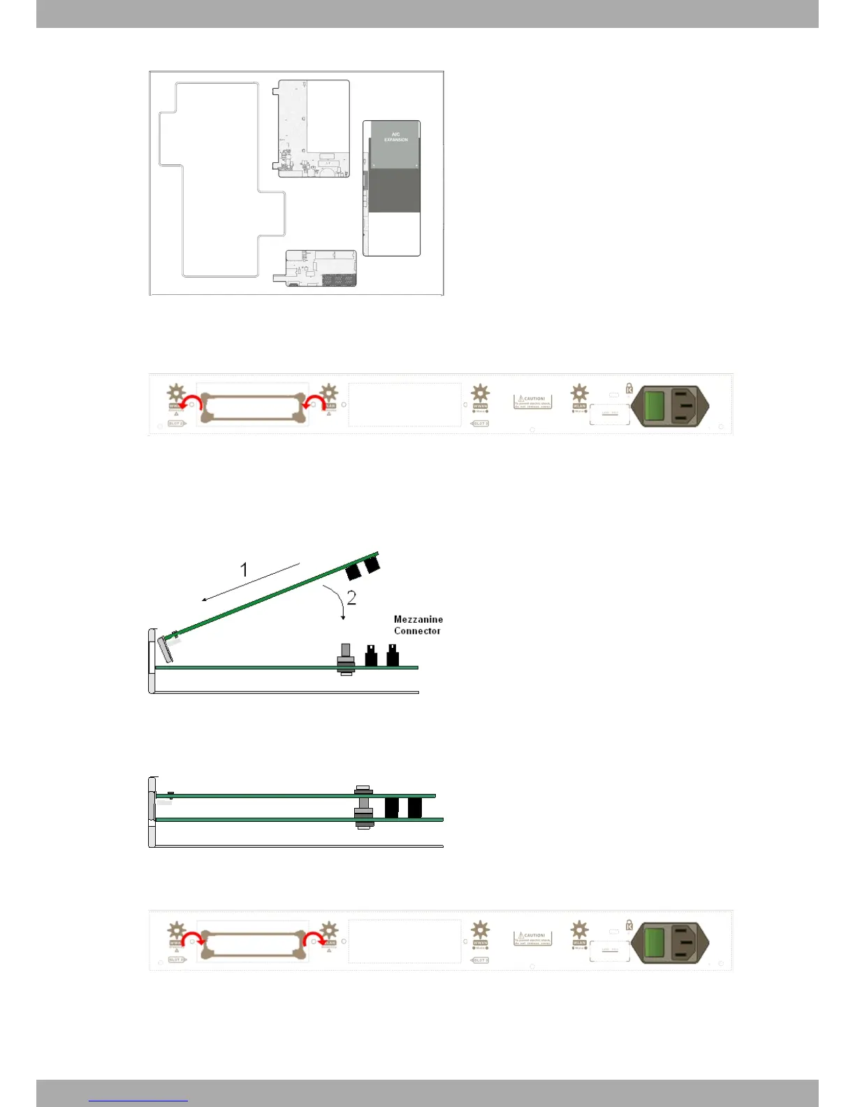
(8) Place the AIC card in the slot so that this firstly adjusts to the space on the device rear panel and subsequently
to the two AIC connections. This operation must be carried out carefully, without forcing any piece or part of the
device. Check that the board is clearly settled over the AIC connectors. Please see Fig. 18 on page 13.
Fig. 18: Inserting the AIC expansion card
(9) Screw the AIC board to the standoff posts using two screws and their corresponding washers. Firmly tighten the
screws without damaging the board.
Fig. 19: Screwing down the AIC expansion card
(10) Reposition the expansion slot cover and screw it down
Fig. 20: Repositioning the SLOT 2 cover
(11) Rearrange the top panel flap and screw it into place using the screws. Please see Fig. 14 on page 11.
(12) Connect and switch on the device, as described in section Connecting on page 19. Should you detect any prob-
lems, switch off the device and make sure that the above steps have been carried out correctly. If the problem
Alcatel-Lucent Enterprise
3 Components and Power Supply
OA58XX Router 13
 Loading...