3.1.4 Side Panel
The following figure shows the side panel.
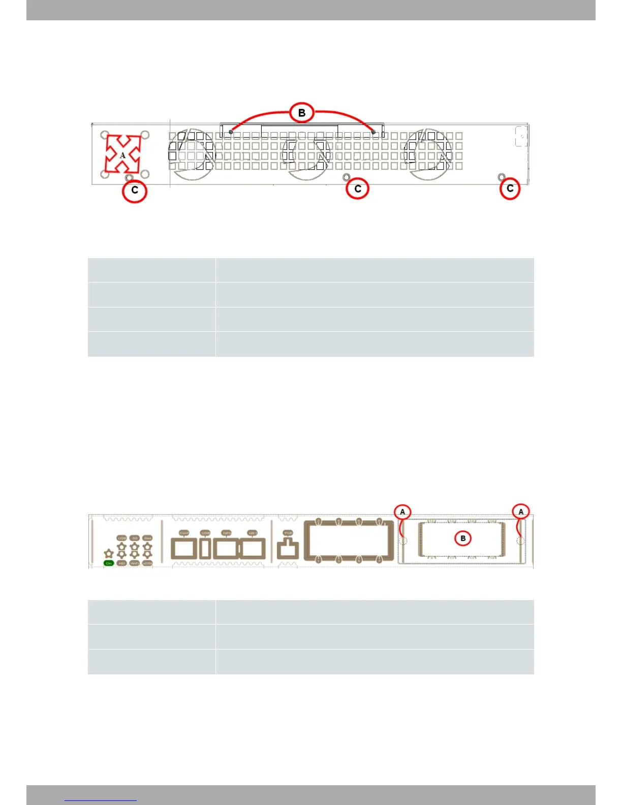
Fig. 7: Side panel
The side panel elements are as follows:
Side panel elements table
Item Description
A Slots for the screws to assemble this in rack.
B Securing screws for the flap on the top panel.
C Securing screws for the top panel
3.2 Expansion Slots
The OA58XX has three expansion slots (SLOT 1, SLOT 2 and SLOT 3), allowing you to increase its features and in-
terfaces by inserting different cards or boards.
3.2.1 SLOT 1 - Expansion Slot
SLOT 1 is located on the right hand side of the device’s Front Panel on page 5. In this case, we insert an eight-port
Switch expansion card.
Fig. 8: SLOT 1 Expansion Slot
SLOT 1 expansion slot elements table
Item Description
A Screws to hold the cover of the expansion module in SLOT 1.
B 8-port Switch Ethernet expansion module.
In order to correctly insert the card, please follow the steps given below:
(1) Switch off the device and remove the cables, as described in section Disconnecting on page 19.
(2) Remove the device from the workplace and place it in a stable, safe location where it can be easily accessed
and handled.
(3) Remove the screws from the side panel in order to be able to dismantle the flap that gives access to the expan-
sion cards. Please see Fig. 9 on page 10.
Alcatel-Lucent Enterprise
3 Components and Power Supply
OA58XX Router 9