Fig. 9: Remove the flap’s screws from the top panel
(4) Once the screws have been removed, slide the flap and lift it (making sure no grooves attach the flap to the top
panel) to remove it. Place it in a safe location.
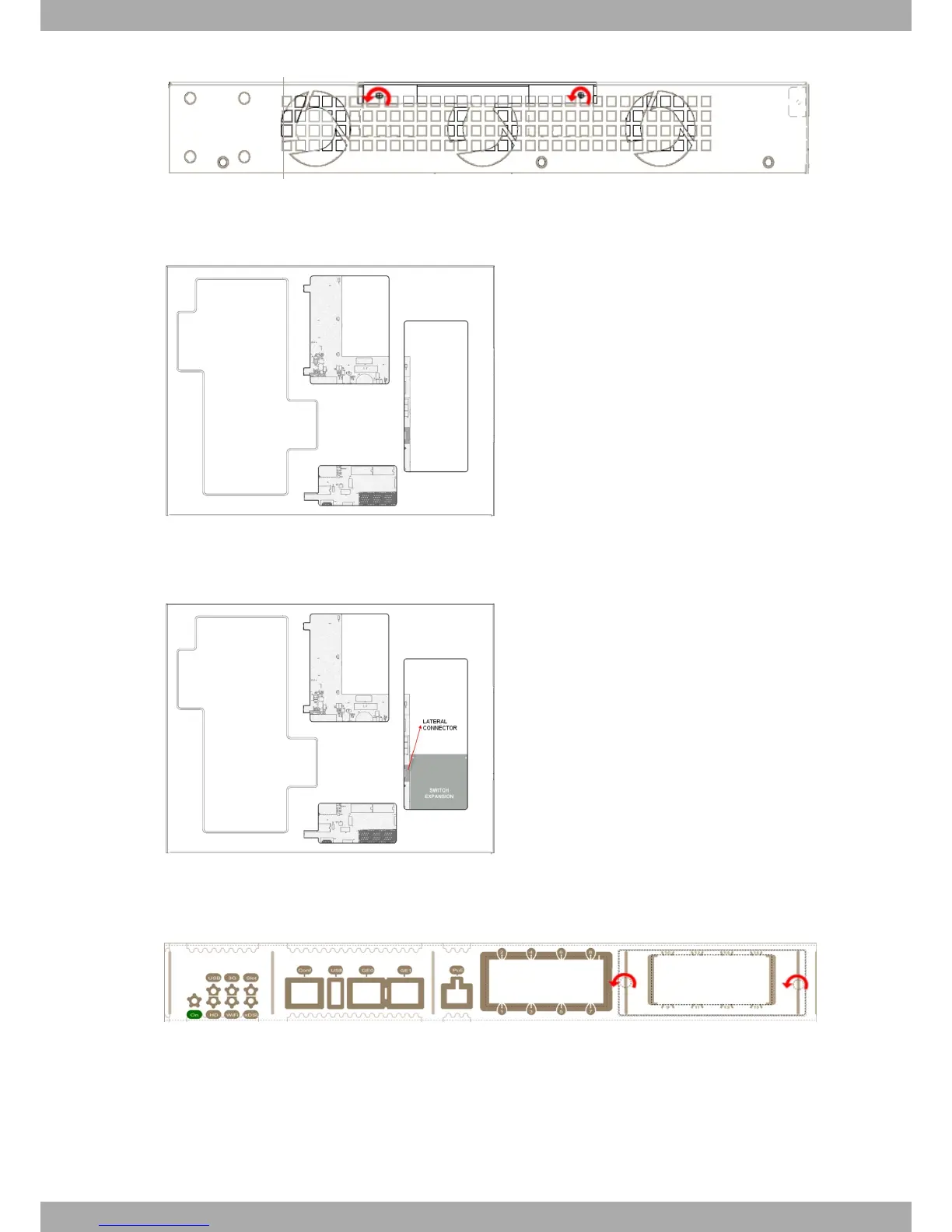
Fig. 10: Top panel without flap
(5) Find the place where the expansion board needs to be located. Look for the lateral connector of the card con-
nection and the card standoff posts to the chassis.
Fig. 11: Location of the lateral connector for SLOT 1 expansion module
(6) Using a screwdriver, remove the cover over the expansion slot. This cover is located on the front panel. Please
see Fig. 12 on page 10.
Fig. 12: Remove the cover from SLOT 1
(7) Insert the expansion board and connect it. This operation must be carried out carefully, without forcing any
piece or part of the device.
(8) Screw in the board. Firmly tighten the screws without damaging the board.
(9) Reposition the expansion slot cover and screw it down. Please see Fig. 13 on page 11.
3 Components and Power Supply Alcatel-Lucent Enterprise
10 OA58XX Router
 Loading...