3. Remove the battery.
4. Remove the wireless card.
5. Remove the M.2 2230 solid-state drive in slot three and four.
6. Remove the M.2 2280 solid state drive or M.2 2230 solid-state drive in slot one and two, whichever applicable.
7. Remove the
small fan.
8. Remove the top heat-sink.
9. Remove the rear-I/O cover.
10.Follow the procedure from step 1 to step 16 in
Removing the system board.
NOTE: The system board can be removed and installed along with the heat sink. This simplifies the removal and installation
procedure and avoids breaking the thermal bond between the system board and heat sink.
About this task
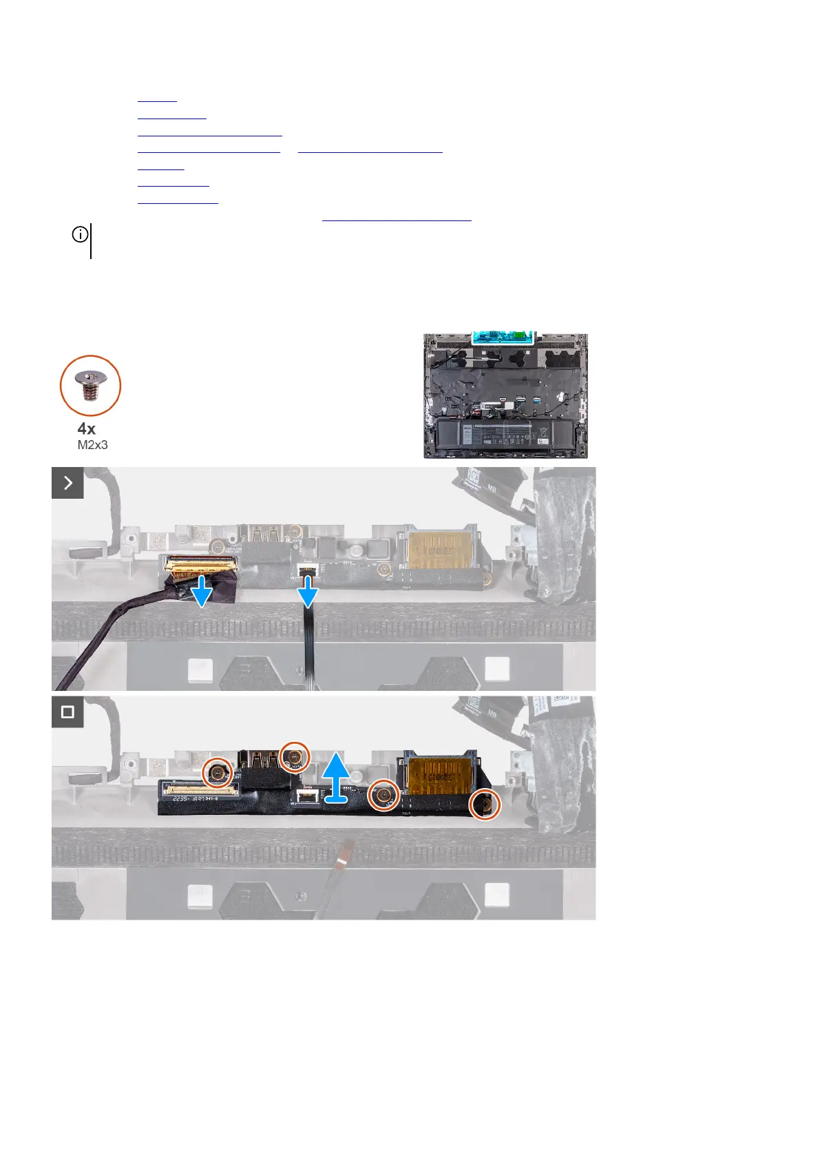
The following image(s) indicate the location of the I/O board and provides a visual representation of the removal procedure.
Steps
1. Peel the tape securing the I/O board cable to the palm-rest and keyboard assembly.
2. Open the latch and disconnect the I/O board cable from the palm-rest and keyboard assembly.
3. Open the latch and disconnect the power-button cable from the palm-rest and keyboard assembly.
4. Remove the four screws (M2x3) that secure the I/O board to the palm-rest and keyboard assembly.
31