3–4 Disassembly and Access Procedures
Publication 1336 IMPACT-6.2 – March 1998
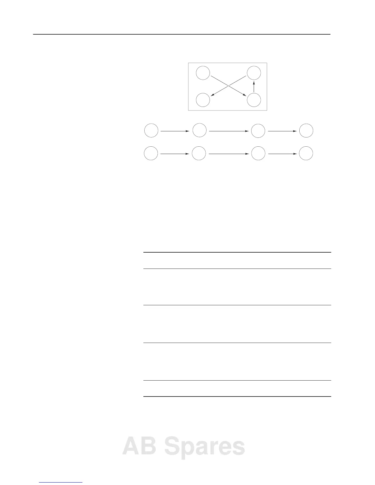
Figure 3.2
Four-Point Mounting
AB0017A
1
2
3
4
1 32 4
4123
Temporary Tighten
Final Tighten
Four-Point Mounting
Torque Specifications
The following table lists fastener locations by component, how the
fasteners are used, and torque specifications. Refer to Torque
Sequence in this chapter for fastening two-point and four-point
components to the heat sink.
Table 3.A
Fastener Torque Specifications
Component
Fastener Application
Torque
lb-in.
Torque
N-m
Bus Capacitor Bank
DC Bus Inductor
DC Bus Inductor
Snubber Board
Snubber Board
Bank to chassis
Wires to bus bars
TB1 mounting plate to chassis
Bus bars to capacitor bank
Board to SCR1
25 – 31
25 – 31
25 – 31
25 – 31
25 – 31
2.8 – 3.5
2.8 – 3.5
2.8 – 3.5
2.8 – 3.5
2.8 – 3.5
Snubber Board
Power Modules PM1 – PM3
Input Rectifier
Bus Fuse F1
Board to PM1 – PM3
Module to heat sink
Rectifier to heat sink
Fuse to chassis
30 – 39
25 – 31
25 – 31
200 – 220
3.4 – 4.4
2.8 – 3.5
2.8 – 3.5
22.6 – 24.8
Thermistor Thermistor to heat sink Hand tighten only
TB1
TB2
TB3
Ground Sense CT
Ground Sense CT
Wires to terminals
Wires to terminals
Wires to terminals
Bracket to chassis
Positive bus bar junction
25 – 31
8
8
25 – 31
25 – 31
2.8 – 3.5
0.9
0.9
2.8 – 3.5
2.8 – 3.5
Ground Sense CT
Main Control Board
Bus bars to capacitor bank
Board to Mounting Plate
25 – 31
12 – 16
2.8 – 3.5
1.4 – 1.8
AB Spares
 Loading...


