Rockwell Automation Publication 1444-UM001D-EN-P - June 2018 171
Measurement Definition Chapter 4
In Tab le 35 , the maximum RPM values available for each Angular Range
selection are presented.
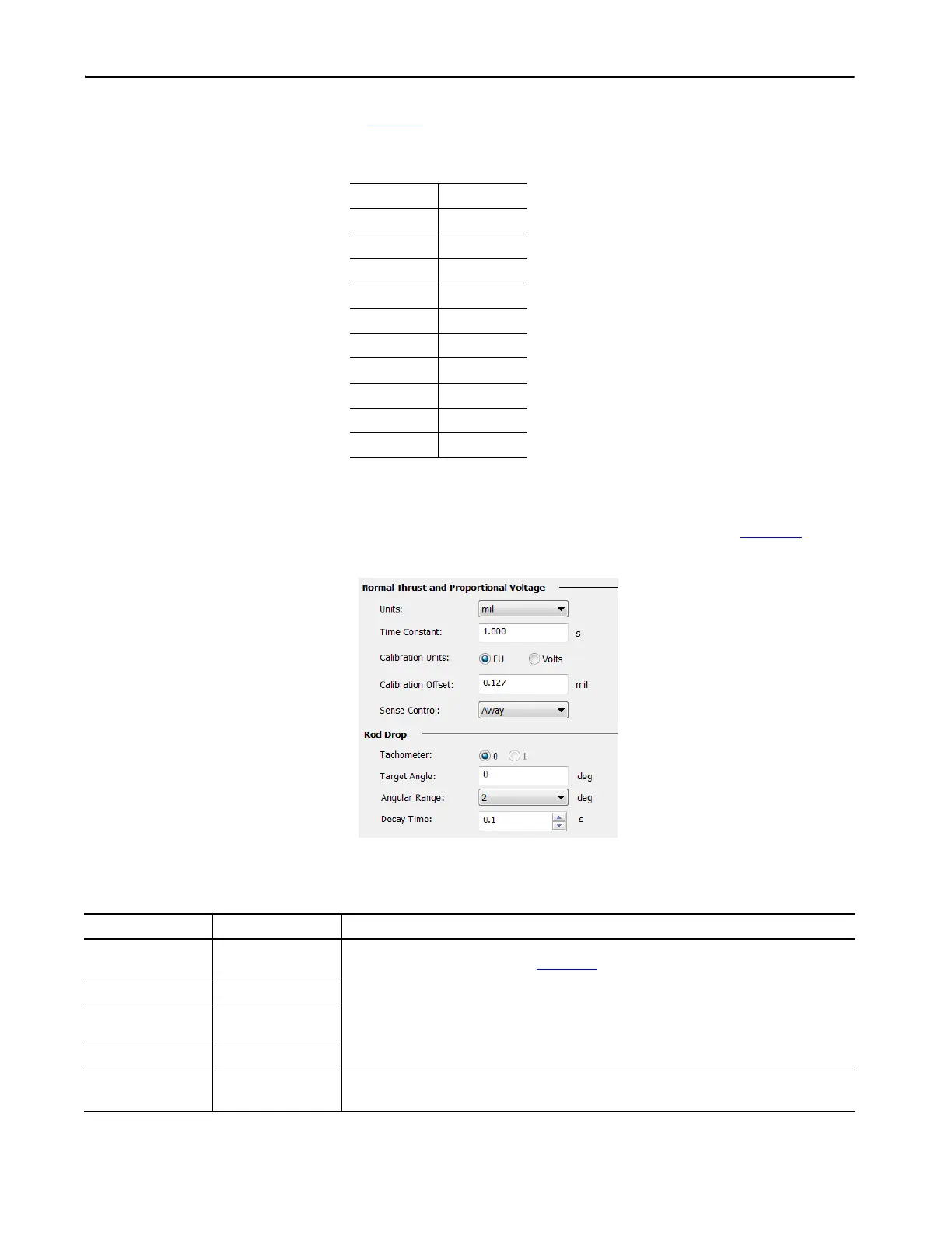
Configuring Rod Drop Measurements
Rod drop measurements are configured using the controls in Figure 65.
Figure 65 - Rod Drop Measurements
Table 35 - Maximum RPM for Angular Range
Angular Range Max RPM
2 976
4 1953
6 2929
8 3905
10 4882
12 5858
14 6834
16 7811
18 8787
20 9763
Table 36 - Configurable Parameters for Rod Drop Measurements
Parameters Values Comments
Units Select from presented
displacement units
Rod drop measurements are made using eddy current probes. Configuration of the units, time constant, calibration
offset, and sense control are the same as for Normal Thrust
measurements.
Time Constant 0.1…60.0 seconds
Calibration Units EU (0)
Volts (1)
Calibration Offset -50,000…50,000
Tachometer 0 (Tacho/Speed 0)
1 (Tacho/Speed 1)
Select the source for the tachometer that is used in the rod drop measurement.
Value that is written to the assembly is 1 or 2, 0 = off (to the module).

 Loading...