216 Rockwell Automation Publication 1444-UM001D-EN-P - June 2018
Chapter 8 Configure Alarms
Transducer
State
Behavior
Select from:
•Transducer Fault Considered
•Transducer Fault Monitored
• Transducer Fault Not Considered
This selection specifies the behavior of the Measurement Alarm if a transducer fault occurs.
Also consider:
Deadband 0…20 Enter a deadband (hysteresis) as a percentage of the alarm limit or alarm window range. This value is
the amount that the measured value must increase above or fall below (the non-alarm state direction)
the limit after exceeding it before the alarm condition clears.
The intent of the deadband is to minimize “chatter”, where a measurement oscillates around the alarm
limit and causes the alarm condition to set and unset repeatedly.
For window alarms, the deadband is the stated percentage of the range of the window (high - low).
Alert Alarm
Delay Time
0.000…65.500 seconds Enter the time that the measured value must persist at an Alert level before an Alert Alarm condition is
set.
The intent of an alarm delay is to help prevent random electronic or mechanically generated noise. This
noise can create rapid, short-lived signal spikes, from being interpreted, and acted on, as if an actual
alarm condition.
Danger Alarm
Delay Time
0.000…65.500 seconds Enter the time that the measured value must persist at a Danger level before a Danger Alarm condition
is set.
The intent of an alarm delay is to help prevent random electronic or mechanically generated noise. This
noise can create rapid, short-lived signal spikes, from being interpreted, and acted on, as if an actual
alarm condition.
Apply Limits
From
Select from:
• Static Limits
• Static Limits with Adaptive Multipliers
• Output Tag Limits
Select the source for the alarm limits and any applicable multipliers.
Adaptive
Limits
— When the Limit Source is “Static Limits w/ Adaptive Multipliers”, click this option to access the Adaptive
Multipliers editor.
Adaptive Multipliers are uniquely defined for each Measurement Alarm.
Danger High
Limit
Any Enter a value to specify the limit that when the measurement is above/below (unsafe direction) defines
a Danger Alarm condition.
Danger low
Limit
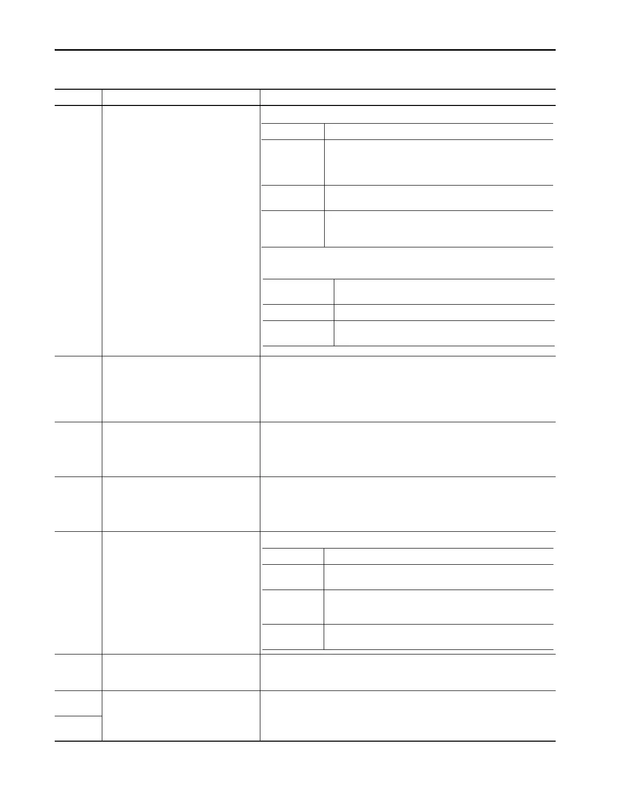
Table 45 - Alarms (continued)
Parameter Values Help
Option Behavior
Transducer Fault
Considered
The Alarm is not evaluated (so never TRUE) if the transducer is in a Fault
condition.
Any alarm that was TRUE (actuated) clears if the associated transducer goes into
fault.
Transducer Fault
Monitored
The Alarm is forced to TRUE (actuated) when the transducer is in a Fault
condition, regardless of the value of the measured parameter.
Transducer Fault
Not Considered
The behavior of the alarm remains strictly defined by the measurement.
Depending on the nature of a transducer fault and the specifics of the
measurement, a fault can force the measurement high, or low.
Dual Channel
Measurements
The preceding table information applies if either sensor faults.
Speed Measurements The preceding table information applies if the speed transducer faults.
Speed Dependent
Measurements
The preceding table information applies if the associated transducer faults
OR if the speed transducer faults.
Option Description
Static Limits The normal mode. The limits are entered directly (so are static), along with one
(static) multiplier that the Setpoint Multiplier function manages.
Static Limits with
Adaptive
Multipliers
The limits are entered directly (so are static), but uses up to five multipliers that
are applied depending on a control parameter.
Output Tag Limits The limits are passed to the module in the Controller Output assembly. No
multiplication is provided.

 Loading...